Apparatus for impact testing for electric generator stator wedge tightness

a technology for stator wedges and electric generators, which is applied in the direction of structural/machine measurement, instruments, transportation and packaging, etc., can solve the problems of stator mica insulation failure, coil grounding or “flashover” of coils, and time-consuming these tests

Active Publication Date: 2010-06-29
SIEMENS ENERGY INC
View PDF34 Cites 17 Cited by
  • Summary
  • Abstract
  • Description
  • Claims
  • Application Information

AI Technical Summary

Problems solved by technology

In the past, the most time consuming of these tests has been the test of stator wedge tightness since, originally, it has required removal of the rotor to gain access to the stator bore area, specifically the tooth tip area where the wedges are located.
Field experience has shown that failure to hold the stator coil stationary in the stator slot permits ever increasing levels of vibration leading to deterioration and finally failure of the stator mica insulation and, in many instances, grounding or “flashover” of the coils.
When this occurs, the owner / operator of the unit is faced with a time-consuming and expensive rewinding process.
One of the difficulties in testing wedge tightness without removal of the rotor is that there is as little as between 0.6 inch (1.52 cm) and 1.5 inches (3.81 cm) of clearance between the stator bore and the rotor retainer ring through which apparatus may be inserted to inspect the wedges distributed along the length of the stator.
Another difficulty is that the wedges are made of non-conducive, non-magnetically permeable material such as, for example, fiberglass coated with Kevlar which is, compared to other materials such as steel, an absorbent of mechanical energy so that the techniques available for measuring tightness are limited.
An additional difficulty, especially in the case of an impact tester, is that the stator coils extend radially outward about a horizontal axis such that the effect of gravity on the impactor varies with the angular position of the stator wedge being tested.
It has also been found that it is difficult to assess with a computer the acoustic response recorded by the microphone.
This method does not discriminate between different degrees of looseness nor does the apparatus have sufficient power to resonate wedges of the size and style used with the larger steam driven units.
In addition, the unit is too large to fit into the rotor stator gap.
This has been confirmed, however, the sensitivity of the test does not permit clear discrimination between the tight and loose conditions.
Furthermore, a version of such a device small enough for use in the air gap of a generator has not been developed.
Furthermore, the size of the system would not permit the current carriage to fit into gaps of less than 0.75 inch (1.90 cm).

Method used


Image

  • Apparatus for impact testing for electric generator stator wedge tightness
  • Apparatus for impact testing for electric generator stator wedge tightness
  • Apparatus for impact testing for electric generator stator wedge tightness

Examples


Embodiment Construction

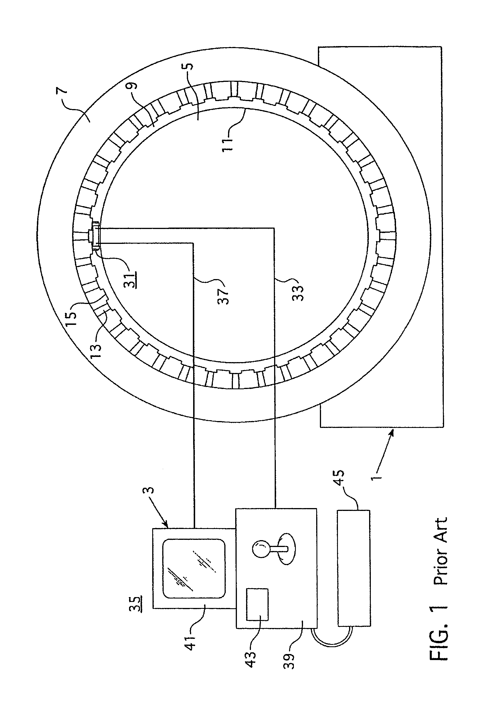
[0025]FIG. 1 schematically illustrates a large steam turbine driven electric power generator 1 with the inspection system 3 of the invention in place for measuring generator stator wedge tightness. The generator 1 includes a rotor 5 mounted for rotation within a stator 7. A narrow air gap 9 is formed between the rotor retainer ring 11 and the stator. In some electric generators, this gap 9 can be as narrow as 0.6 inches (1.52 cm). The stator 7 includes stator coils 13 positioned between longitudinally extending stator teeth 15.

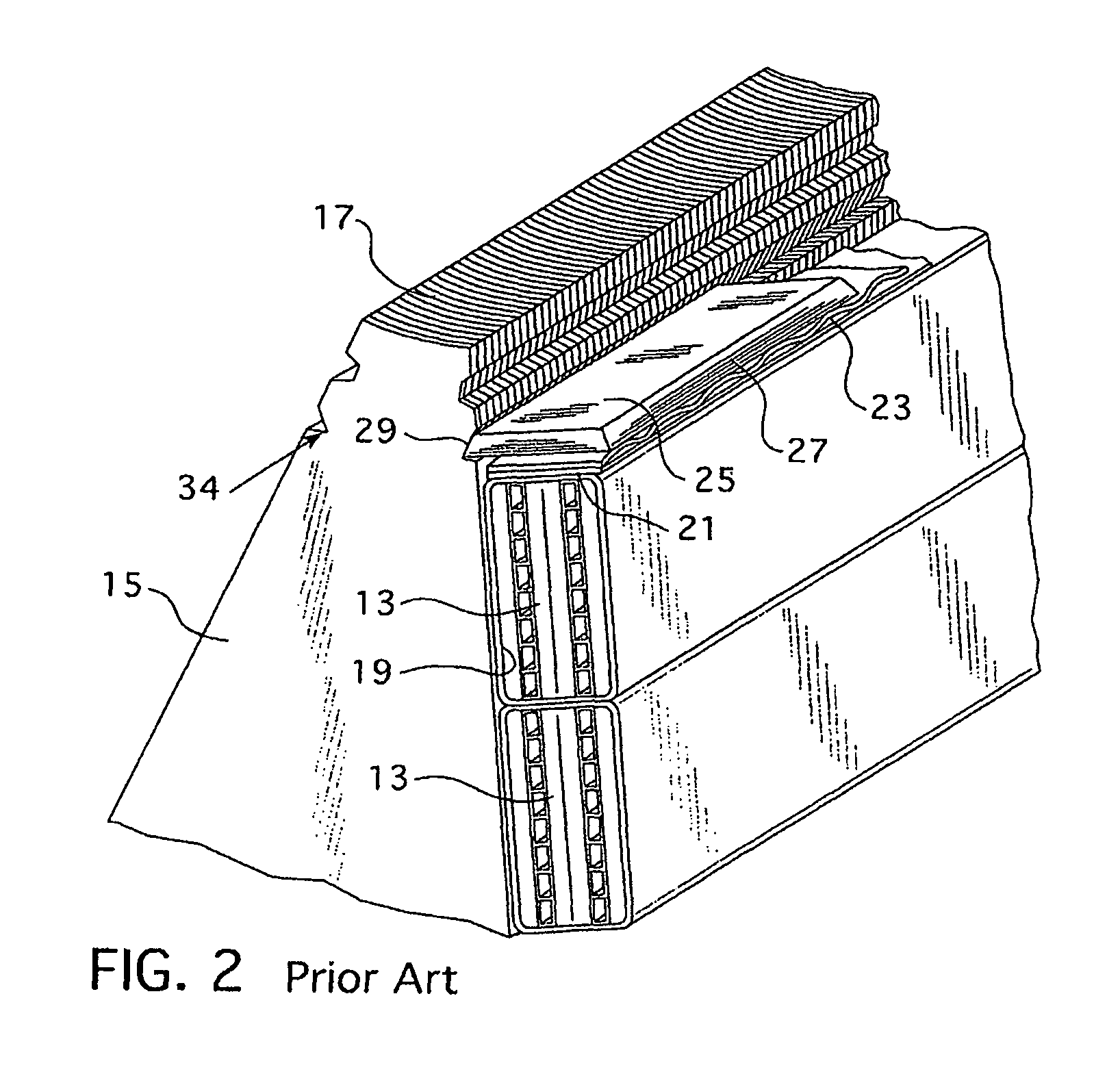
[0026]As shown more clearly in FIG. 2, the stator teeth 15 which are made of laminations 17 form stator slots 19 in which stator coils 13 are stacked in pairs, one on top of the other. The stator coils 13 are retained in the slots 19 by shims 21, sections of ripple springs 23, and stator wedges 25 having beveled edges 27 which engage correspondingly shaped grooves 29 in the sidewalls of the stator teeth 15. The ripple spring sections 23 are compressed between ...


PUM


Abstract

A remote-controlled dynamoelectric machine inspection vehicle that can fit and travel within a narrow air gap between a stator and rotor of a dynamoelectric machine. The inspection vehicle has an effectuator that can remotely activate a hammer driven by a high pressure pneumatic three-stage miniature piston that propels the hammer against a stator slot wedge creating an impact force that causes the wedge to vibrate. The vibrations are sensed to determine the tightness of the wedge.

Description

BACKGROUND OF THE INVENTION[0001]1. Field of the Invention[0002]This invention relates to apparatus for remotely testing dynamoelectric machine stator wedge tightness with the rotor in place. More particularly, this invention relates to apparatus which includes a remotely controlled carriage small enough to fit into the air gap between the rotor and stator of a dynamoelectric machine, which carries an impactor to induce vibrations in the wedges which are measured by a sensor to provide information on wedge tightness.[0003]2. Description of the Prior Art[0004]During scheduled and some forced outages of dynamoelectric machines, such as electric utility steam driven electric generators, one of the major concerns is the condition of the stator coils. Many tests are performed to quantify stator integrity. In the past, the most time consuming of these tests has been the test of stator wedge tightness since, originally, it has required removal of the rotor to gain access to the stator bore...

Claims


Application Information

Patent Timeline
Patent Type & Authority Patents(United States)
IPC IPC(8): G01M7/00G01M19/00B62D55/00G01M99/00
CPCG01M7/08
Inventor MOORE, CHARLES C.
Owner SIEMENS ENERGY INC
Why Eureka
Try Eureka