3D ultrasound-based instrument for non-invasive measurement of amniotic fluid volume

a 3d ultrasound and amniotic fluid technology, applied in the field of obstetrics, can solve the problems of poor correlation between the afi and the true af volume, invasive and cumbersome methods, and not being routinely used, and achieve the effect of robust positioning

Inactive Publication Date: 2010-06-29
VERATHON
View PDF19 Cites 46 Cited by
  • Summary
  • Abstract
  • Description
  • Claims
  • Application Information

AI Technical Summary

Benefits of technology

[0027]In a preferred image enhancement process, each 2D image in the 3D dataset is first enhanced using non-linear filters by an image pre-filtering step. The image pre-filtering step includes an image-smoothing step to reduce image noise followed by an image-sharpening step to obtain maximum contrast between organ wall boundaries.

Problems solved by technology

Polyhydramnios and oligohydramnios are diagnosed in about 7-8% of all pregnancies and these conditions are of concern because they may lead to birth defects or to delivery complications.
Even though the AFI measure is routinely used, studies have shown a very poor correlation of the AFI with the true AF volume (Sepulveda W, Flack N J, Fisk N M., “Direct volume measurement at midtrimester amnioinfusion in relation to ultrasonographic indexes of amniotic fluid volume,” Am J Obstet Gynecol April; 170(4): 1160-3, 1994).
This technique is the accepted gold standard for AF volume measurement; however, it is an invasive and cumbersome method and is not routinely used.
This technique is obviously dependent on observer experience and has not been found to be very good or consistent at diagnosing oligo- or poly-hydramnios.
However, the Segiv et al. method is interactive in nature and the identification of amniotic fluid volume is very observer dependent.
Moreover, the system described is not a dedicated device for amniotic fluid volume assessment.
Amniotic fluid pockets having shapes not consistent with the Grover et al. bladder model introduces analytical errors.
Moreover, the bladder volume instrument does not allow for the possibility of more than one amniotic fluid pocket in one image scan.
Therefore, the amniotic fluid volume measurements made by the Grover et al. system may not be correct or accurate.
None of the currently used methods for AF volume estimation are ideal.

Method used


Image

  • 3D ultrasound-based instrument for non-invasive measurement of amniotic fluid volume
  • 3D ultrasound-based instrument for non-invasive measurement of amniotic fluid volume
  • 3D ultrasound-based instrument for non-invasive measurement of amniotic fluid volume

Examples


Embodiment Construction

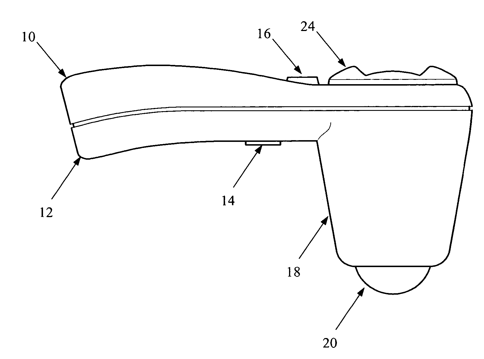
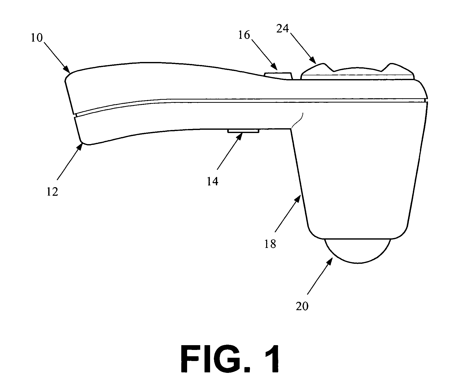
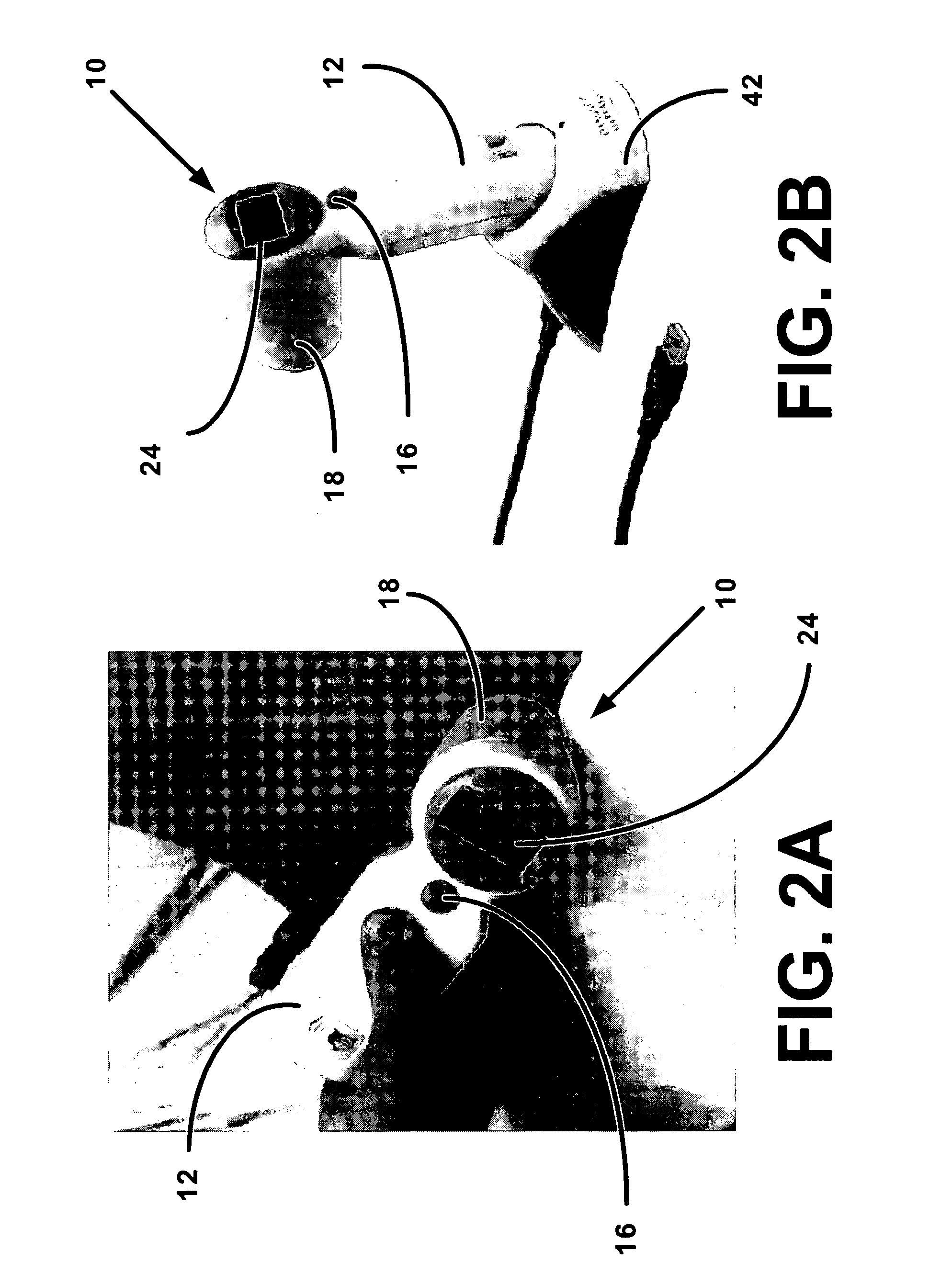
[0079]The preferred portable embodiment of the ultrasound transceiver of the amniotic fluid volume measuring system are shown in FIGS. 1-4. The transceiver 10 includes a handle 12 having a trigger 14 and a top button 16, a transceiver housing 18 attached to the handle 12, and a transceiver dome 20. A display 24 for user interaction is attached to the transceiver housing 18 at an end opposite the transceiver dome 20. Housed within the transceiver 10 is a single element transducer (not shown) that converts ultrasound waves to electrical signals. The transceiver 10 is held in position against the body of a patient by a user for image acquisition and signal processing. In operation, the transceiver 10 transmits a radio frequency ultrasound signal at substantially 3.7 MHz to the body and then receives a returning echo signal. To accommodate different patients having a variable range of obesity, the transceiver 10 can be adjusted to transmit a range of probing ultrasound energy from appro...


PUM


Abstract

A hand-held 3D ultrasound instrument is disclosed which is used to non-invasively and automatically measure amniotic fluid volume in the uterus requiring a minimum of operator intervention. Using a 2D image-processing algorithm, the instrument gives automatic feedback to the user about where to acquire the 3D image set. The user acquires one or more 3D data sets covering all of the amniotic fluid in the uterus and this data is then processed using an optimized 3D algorithm to output the total amniotic fluid volume corrected for any fetal head brain volume contributions.

Description

PRIORITY CLAIM[0001]This U.S. patent application Ser. No. 11 / 362,368 filed Feb. 24, 2006 claims priority to U.S. provisional patent application Ser. No. 60 / 760,677 filed Jan. 20, 2006.[0002]This U.S. patent application Ser. No. 11 / 362,368 filed Feb. 24, 2006 is a continuation of PCT application serial number PCT / US05 / 043836 filed Dec. 6, 2005 and to U.S. patent application Ser. No. 11 / 295,043 filed Dec. 6, 2005 that claims priority to U.S. provisional patent application Ser. No. 60 / 633,485 filed Dec. 6, 2004.[0003]This U.S. patent application Ser. No. 11 / 362,368 filed Feb. 24, 2006 is a continuation of PCT application serial number PCT / US05 / 30799 filed Aug. 29, 2005 which claims priority to U.S. patent application Ser. No. 11 / 213,284 filed Aug. 26, 2005 that claims priority to U.S. provisional patent application Ser. No. 60 / 608,426 filed Sep. 9, 2004 and 60 / 605,391 filed Aug. 27, 2004.[0004]This U.S. patent application Ser. No. 11 / 362,368 filed Feb. 24, 2006 is a continuation of PCT...

Claims


Application Information

Patent Timeline
Patent Type & Authority Patents(United States)
IPC IPC(8): A61B8/08A61B5/00A61B8/00A61B8/12A61B8/14G06T5/00G06T7/60G06V10/24G06V10/26
CPCA61B5/204A61B8/0858A61B8/0866A61B8/483A61B8/565G01S7/52065G01S15/8993G06K9/32G06K9/34G06T7/0012G06T7/0083G06T7/0087G06T7/0091G06T7/602A61B5/4343G06T2207/30044A61B8/14A61B8/4472G06K2209/05G06T2207/10136G06T2207/20061G06T2207/30004G06T7/12G06T7/143G06T7/155G06T7/62G06V10/24G06V10/26G06V2201/03
Inventor CHALANA, VIKRAMMCMORROW, GERALDDUDYCHA, STEPHEN JAMES
Owner VERATHON
Why Eureka
Try Eureka