Sample inspection method, sample inspection apparatus, and sample holder

a sample inspection and sample technology, applied in the direction of material analysis using wave/particle radiation, instruments, etc., can solve the problems of deteriorating the resistance of the film to the pressure difference, damage to the film, and gradual destruction of the coupling between the molecules forming the film, etc., to achieve the effect of simple structur

Active Publication Date: 2010-06-29
JEOL LTD
View PDF2 Cites 12 Cited by
  • Summary
  • Abstract
  • Description
  • Claims
  • Application Information

AI Technical Summary

Benefits of technology

[0013]Accordingly, it is an object of the present invention to provide an inexpensive sample holder which is used when a sample is inspected by directing a primary beam consisting of a charged-particle beam (such as an electron beam) at the sample via a film as described previously and which is simple in structure.
[0014]The primary beam irradiation of the film produces damage to the film. That is, when the electron beam enters the film, coupling between molecules forming the film is gradually destroyed. This deteriorates the resistance of the film to the pressure difference between vacuum and atmospheric pressure.
[0017]In view of the foregoing problem, it is another object of the present invention to provide a method of inspecting a sample in such a way that when the sample is irradiated with a primary beam, such as an electron beam, via a film for the inspection, damage to the film due to beam irradiation is detected and thus destruction of the film due to a pressure difference can be prevented. It is a further object of the present invention to provide a sample inspection apparatus adapted to implement this method.
[0020]A second sample inspection apparatus according to another embodiment of the present invention has: two films disposed opposite to each other such that a sample is held between mutually opposite surfaces of the films; a vacuum chamber for reducing the pressure of an ambient in contact with surfaces of the films facing away from the mutually opposite surfaces; irradiation apparatus connected with the vacuum chamber and irradiating the sample with a primary beam via one of the films; and signal detection apparatus for detecting a secondary signal produced from the sample in response to the beam irradiation. The sample inspection apparatus includes: a monitoring device for monitoring information about the film obtained in response to the irradiation and / or a monitoring device for monitoring a dose of the primary beam impinging on the film.
[0023]Consequently, when the damage to the film has increased to a considerable degree, destruction of the film due to the pressure difference can be prevented by stopping the beam irradiation of the film. This assures that the inside of the apparatus is prevented from being contaminated.
[0024]Furthermore, according to the present invention, a sample holder which is simple in structure and can be fabricated at low cost can be offered.

Problems solved by technology

The primary beam irradiation of the film produces damage to the film.
That is, when the electron beam enters the film, coupling between molecules forming the film is gradually destroyed.
This deteriorates the resistance of the film to the pressure difference between vacuum and atmospheric pressure.
If the strength of the film deteriorates due to beam irradiation damage, the film may no longer withstand the pressure difference.
Where the film damaged as described above is destroyed by the pressure difference, the liquid component of the sample (containing moisture) held on the film leaks into the sample chamber.
This will contaminate the inside of the SEM instrument.

Method used


Image

  • Sample inspection method, sample inspection apparatus, and sample holder
  • Sample inspection method, sample inspection apparatus, and sample holder
  • Sample inspection method, sample inspection apparatus, and sample holder

Examples


first embodiment

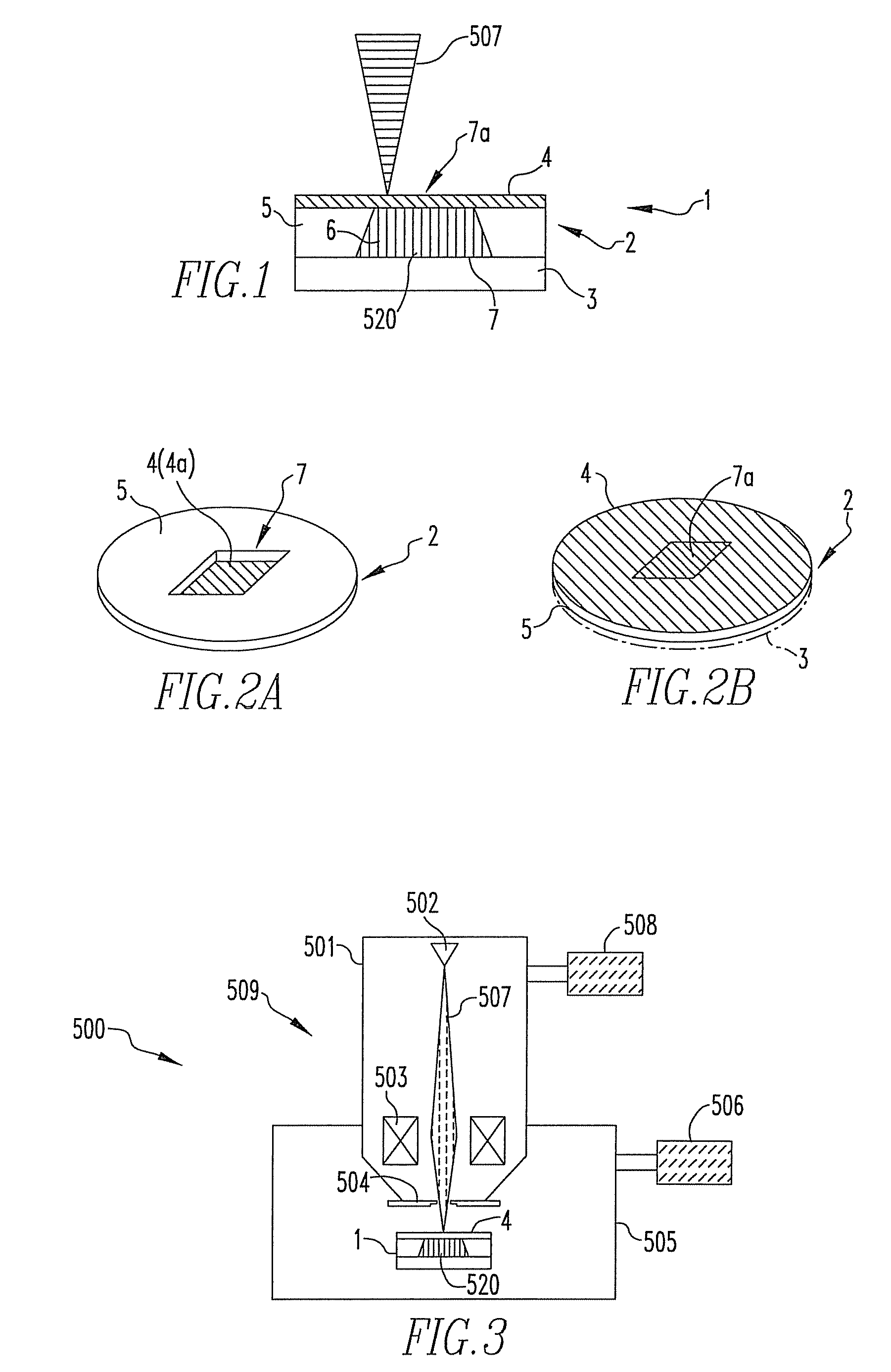
[0040]FIG. 1 is a schematic cross section of a sample holder 1 for use in the present invention. The holder 1 is composed of a sample-holding member 2 and a base plate 3 which are bonded together with adhesive (not shown). The base plate 3 is made of silicon.

[0041]The sample-holding member 2 has a fixing member 5 and a sample-holding film 4. The fixing member 5 is provided with an opening 7 for forming a sample-holding space 6. The film 4 is coated on one surface of the fixing member 5 including the opening 7. A sample 520 is held in the sample-holding space 6. The film 4 is made of silicon nitride.

[0042]The sample-holding member 2 constructed in this way is shown in the perspective views of FIGS. 2A and 2B. In FIG. 2A, the sample-holding member 2 is in a state in which the other surface of the fixing member 5 forming the sample-holding member 2 faces upward. In FIG. 2B, the sample-holding member 2 has been rotated in reverse through 180° from the state shown in FIG. 2A. That is, on...

second embodiment

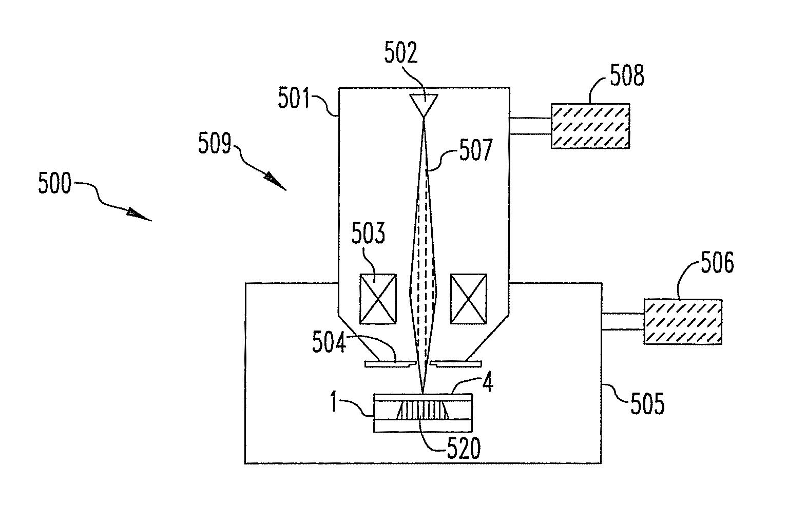
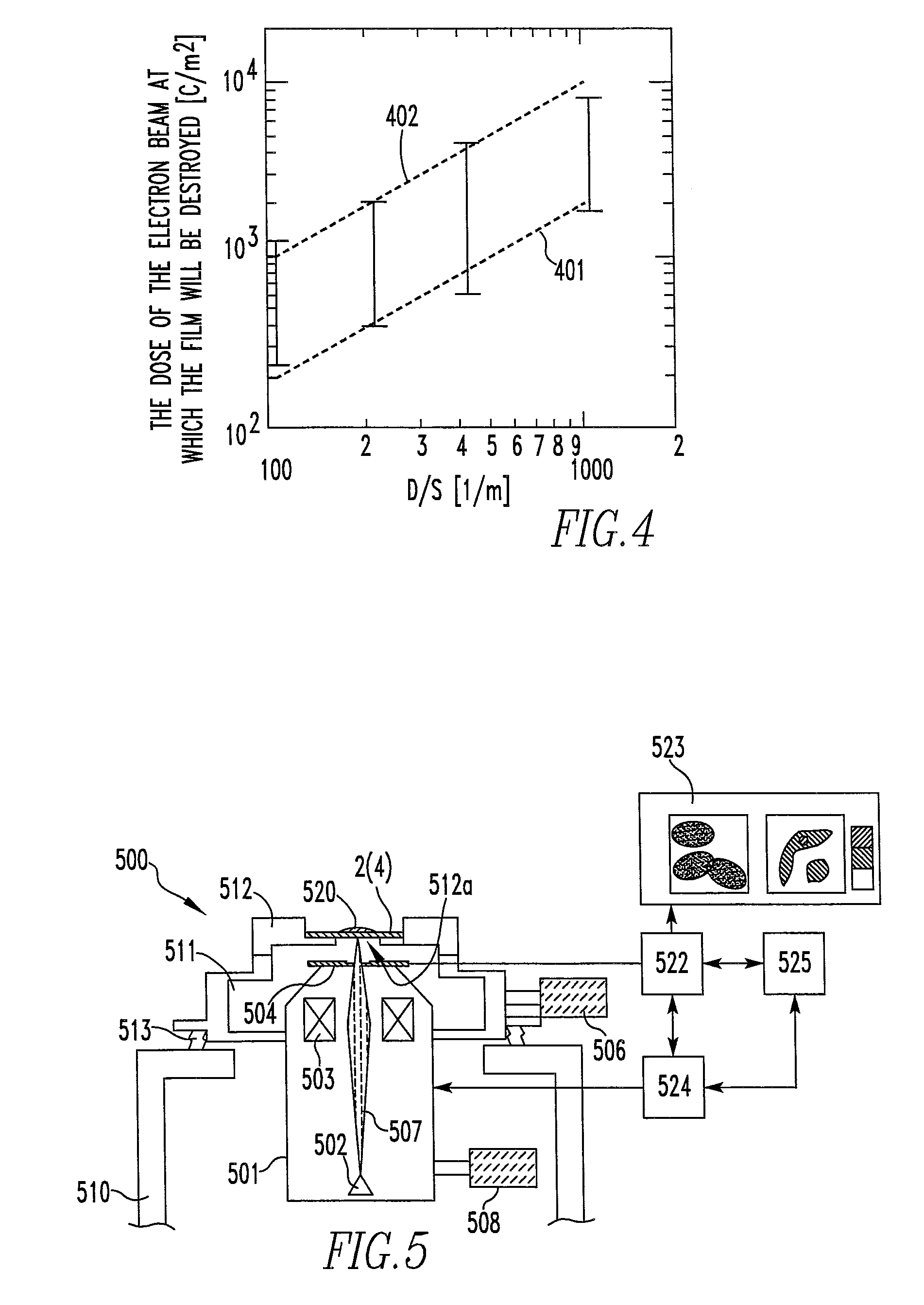
[0056]FIG. 5 is a schematic diagram of a sample inspection apparatus according to the second embodiment of the present invention. In the present apparatus, an electron optical column that is mounted in a normal SEM is inverted. Furthermore, in the present apparatus, the sample 520 is placed in an open space located above the film 4 of the sample-holding member 2.

[0057]The sample-holding member 2 is identical in structure with the structure already described in the first embodiment in connection with FIG. 2A. Any surface of the film 4 formed on the sample-holding member 2 may be used as a top surface on which the sample is placed. However, the sample 520 needs to be placed on the region 7a of the film 4 irradiated with the primary beam. The surface (hereinafter may be referred to as the second surface) of the film 4 facing away from the surface on which the sample is placed is exposed to the ambient inside the vacuum chamber 511. Consequently, the second surface of the film 4 is expo...

third embodiment

[0102]In the above-described first and second embodiments, the dose of the electron beam impinging on a film is recorded. The dose (accumulated dose) is prevented from far exceeding a preset reference value. In contrast, in the present embodiment, information about a film produced in response to electron beam irradiation is detected. Thus, a symptom of destruction of the film is captured. Consequently, destruction of the film is prevented.

[0103]That is, as the film is irradiated with the electron beam, the film is gradually damaged by the beam. Therefore, information based on a secondary signal derived from the film also varies gradually. Variations in the film are detected by detecting the secondary signal as information. A symptom of destruction of the film is captured by monitoring the secondary signal.

[0104]One example of information based on backscattered electrons produced from the film irradiated with an electron beam is information about the film, the latter information bein...


PUM

PropertyMeasurementUnit
pressureaaaaaaaaaa
thicknessaaaaaaaaaa
thicknessaaaaaaaaaa

Abstract

A sample holder is offered which is used when a sample is inspected by irradiating the sample with a primary beam consisting of a charged-particle beam (such as an electron beam) via a film. Furthermore, method and apparatus for preventing destruction of the film due to a pressure difference by detecting damage to the film during inspection are offered.

Description

BACKGROUND OF THE INVENTION[0001]1. Field of the Invention[0002]The present invention relates to a method of inspecting a sample by irradiating it with a primary beam, such as a charged-particle beam, via a film and detecting a secondary signal emanating from the sample in response to the irradiation. Furthermore, the present invention relates to a sample inspection apparatus adapted for use in this method. The present invention also relates to a sample holder adapted to be used in this method.[0003]2. Description of Related Art[0004]In a sample inspection apparatus incorporating the facilities of a scanning electron microscope (SEM), a sample to be investigated is normally placed within a sample chamber whose inside has been evacuated by means of pumping. The sample placed in the sample chamber that is in the reduced pressure ambient is irradiated with a primary beam, such as a charged-particle beam (e.g., an electron beam). As a result, various secondary signals, such as backscatt...

Claims


Application Information

Patent Timeline
Patent Type & Authority Patents(United States)
IPC IPC(8): G01N23/00
CPCG01N23/225H01J37/20H01J37/28H01J37/265H01J2237/2485H01J2237/2003
Inventor NISHIYAMA, HIDETOSHI
Owner JEOL LTD
Why Eureka
Try Eureka