
VA metering in polyphase systems

a polyphase system and metering technology, applied in the field of electricity measurements, can solve the problems of not not necessarily reflecting the amount of energy, or the amount of load watts or load watt-hours, and not necessarily accurately relating to the size of the servi

Active Publication Date: 2010-06-29
LANDIS GYR LLC
View PDF13 Cites 27 Cited by
  • Summary
  • Abstract
  • Description
  • Claims
  • Application Information

AI Technical Summary

Benefits of technology

"The invention is a meter that can automatically calculate the voltage at the source or the load in an electricity system based on the user's selection. The meter uses a processing circuit and an A / D converter to generate digital samples of voltage and current waveforms, which are then used to calculate the voltage at the source or the load. The result is a more efficient and accurate way to measure voltage in a polyphase system."

Problems solved by technology

However, the amount of watts supplied to a load does not necessarily reflect the amount of energy that must be produced by the source.
In particular, the amount of load watts, or load watt-hours, does not necessarily accurately relate to the size of the service (transformers size, size of power lines, etc.) needed to supply the load.
While the actual watt-hour consumption of the second load is the same as the first load, the second load requires more current, which can affect sizing of power lines, transformers, etc.
To this end, in a case of a customer that consumes significantly more VA than watts, the metering of only watt-hours results in a case in which the revenue from the customer does not directly cover the customer's proportional cost of the power delivery equipment.
However, if harmonics are present in the power line signal, then the calculations of VA and the practical significance of the calculated VA becomes more complex.
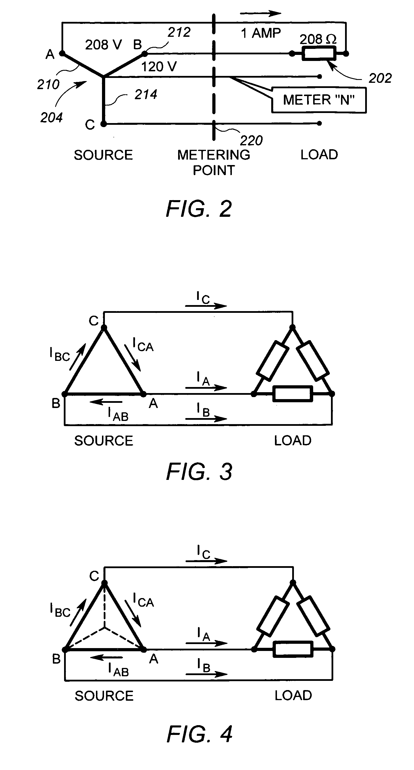
In a polyphase system, the calculation of VA is more complex and the practical significance of what is calculated goes beyond that of single phase systems.
In particular, the two methods of calculating VA (or VA-hours) described above for single phase systems do not necessarily yield the same results if applied to polyphase systems even under conditions of pure sine wave signals.

Method used


Image

  • VA metering in polyphase systems
  • VA metering in polyphase systems
  • VA metering in polyphase systems

Examples


Embodiment Construction

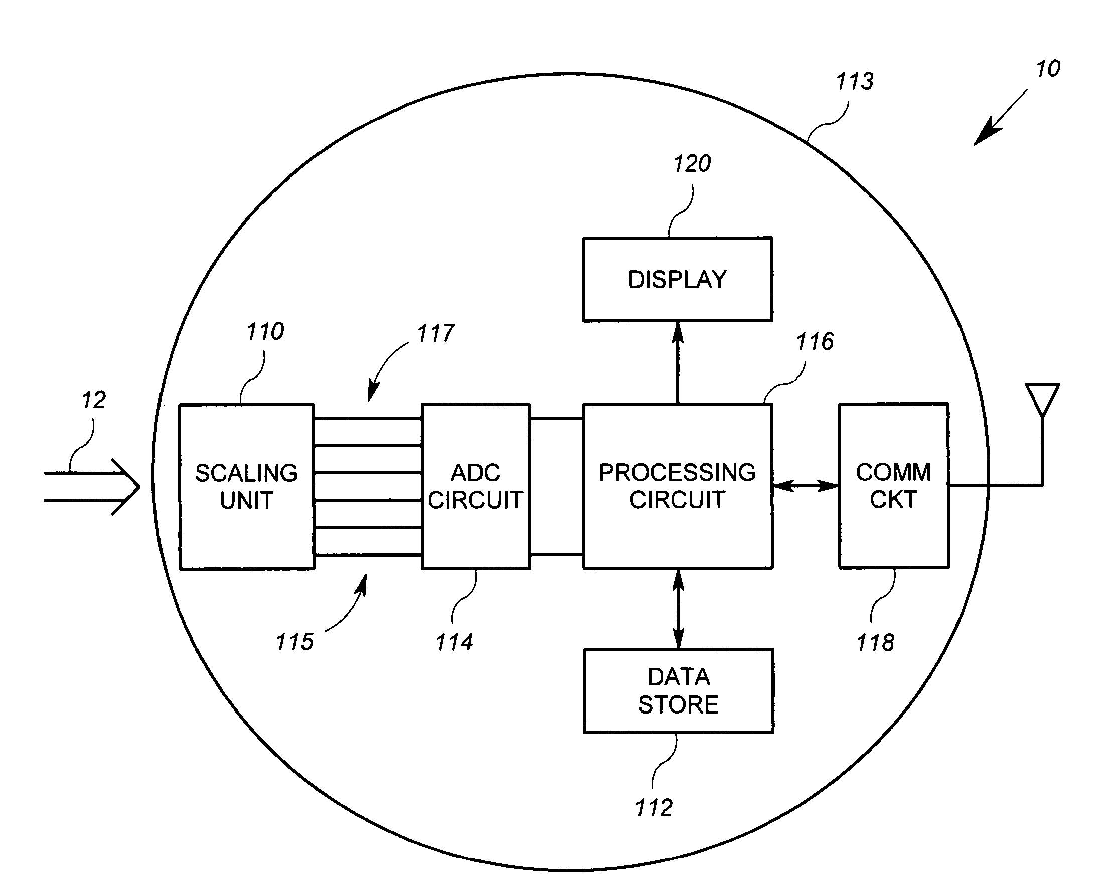
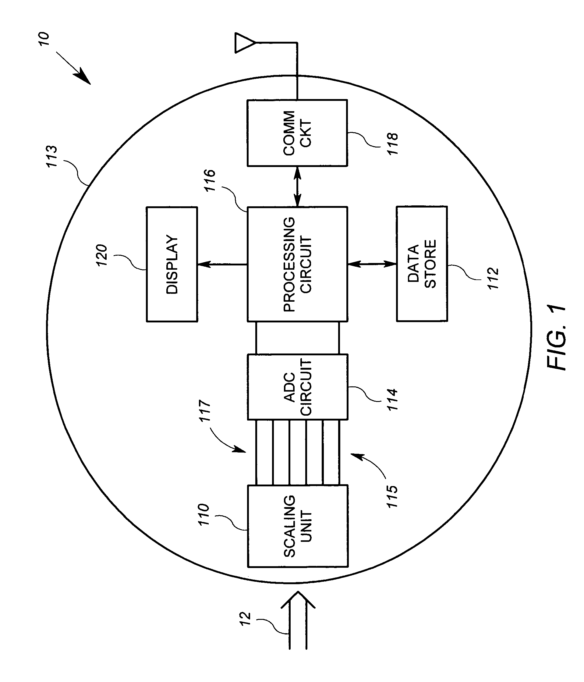
[0024]FIG. 1 shows an exemplary embodiment of a polyphase electricity meter 10 in which an arrangement according the invention is implemented. Referring to FIG. 1 specifically, the metering unit 10 is an apparatus for measuring energy consumption that includes a scaling circuit 110, an analog to digital conversion (“ADC”) circuit 114, a processing circuit 116, a communication circuit 118, an optional display 120 and a data store 122. All of the above listed elements are preferably supported by a meter housing 113, which may take a plurality of known forms. The communication circuit 118 may be disposed within an interior of the meter housing 113 like the other devices, or may be affixed to the outside of the meter housing 113.

[0025]In the embodiment described herein, the scaling circuit 110 and the ADC circuit 114 are arranged to generate digital signals representative of line voltage waveforms for each of three phases of an electrical system and other digital signals representative ...


PUM


Abstract

An arrangement includes an A / D converter and a processing circuit. The A / D converter is configured to generate digital samples of voltage and current waveforms in a polyphase electrical system. The processing circuit is operably coupled to receive the digital samples from the A / D converter. The processing circuit is further configured to combine a value substantially equal to two times the magnitude of the phase A current sample with the phase C current sample to generate a first value, and generate a VA calculation using the first value and at least one other value. The processing circuit is further configured to provide information representative of the VA calculation to one of a group consisting of a display, a communication circuit, and a billing calculation unit.

Description

[0001]This application claims the benefit of U.S. Provisional Patent Application Ser. No. 60 / 850,144, filed Oct. 6, 2006, which is incorporated herein by reference.FIELD OF THE INVENTION[0002]The present invention relates generally to electricity measurements, and more particularly, to VA measurements.BACKGROUND[0003]One of the goals of electricity metering is to accurately measure the use or consumption of electrical energy resources. With such measurements, the cost of generating and delivering electricity may be allocated among consumers in relatively logical manner. Another goal of electricity metering is help identify electrical energy generation and delivery needs. For example, cumulative electricity consumption measurements for a service area can help determine the appropriate sizing of transformers and other equipment.[0004]Electricity metering often involves the measurement of consumed power or energy in the form of watts or watt-hours. Watt-hour measurements relate directl...

Claims


Application Information

Patent Timeline
Patent Type & Authority Patents(United States)
IPC IPC(8): G01R25/00G01R19/00G01R7/00
CPCG01R21/1331
Inventor VOISINE, JOHN
Owner LANDIS GYR LLC
Learn More