Wire bonding method, wire bonding apparatus, and wire bonding control program

a wire bonding control and wire bonding technology, applied in the direction of soldering apparatus, manufacturing tools,auxillary welding devices, etc., can solve the problems of difficult to keep the value of lhb>1/b> not to exceed 50 m, and the length of the loop is not to exceed two times the diameter of the wire, so as to maintain the strength required at the neck portion of the wire.

Active Publication Date: 2010-07-06
KAIJOO KK
View PDF33 Cites 7 Cited by
  • Summary
  • Abstract
  • Description
  • Claims
  • Application Information

AI Technical Summary

Benefits of technology

[0038]In other words, according to the invention, since the capillary presses the side surface of the contact-bonded ball at the first bonding point while moving downward toward the second bonding point, a force in the horizontal direction applied to the contact-bonded ball is reduced and an influence on the joint between the pad and the contact-bonded ball is negligible, so that the joint strength between the pad and the contact-bonded ball is maintained and, in addition, formation of the loop having the height not exceeding two times the wire diameter is achieved.
[0039]According to the invention, the cross sectional area at the joint portion between the contact-bonded ball at the first bonding point and the neck portion of the wire is increased, and the strength required at the neck portion of the wire is maintained.

Problems solved by technology

However, in a loop forming method disclosed in JP-A-2004-172477, it is difficult to keep the sum of the ball thickness T1, the thickness T2 of the wire turnover portion 50, and the height T3 of a protrusion of the loop not to exceed 25 μm using the wire having a diameter of 25 μm, and hence when the wire diameter T4 is added thereto, it is difficult to keep the value of LH1 not to exceed 50 μm.
According to these documents, since the wire is further pressed against the upper portion of the contact-bonded ball, it is difficult to keep the loop height not to exceed two times the wire diameter as in JP-A-2004-172477.

Method used


Image

  • Wire bonding method, wire bonding apparatus, and wire bonding control program
  • Wire bonding method, wire bonding apparatus, and wire bonding control program
  • Wire bonding method, wire bonding apparatus, and wire bonding control program

Examples


Embodiment Construction

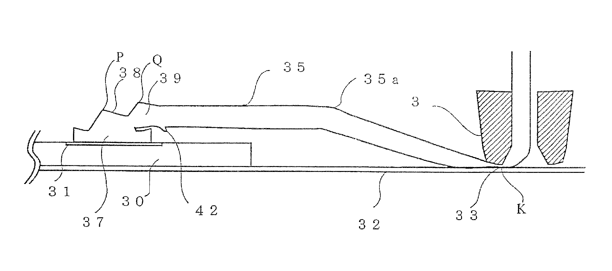
[0052]Referring now to the drawings, best modes for implementing a wire bonding method, a wire bonding apparatus, and a wire bonding control program according to the invention will be described. The invention is adapted to provide two pressing steps; the first pressing step is moving the capillary downward toward a second bonding point after bonding a ball on the first bonding point and then moving the capillary upward to press a side surface of the ball obliquely, and the second pressing step is moving the capillary downward toward the second bonding point after having moved it upward by a predetermined amount following the first bonding step to press the wire obliquely, so that further reduction in the height of a loop is achieved and a sufficient wire pull strength is achieved even in such a low-loop shape.

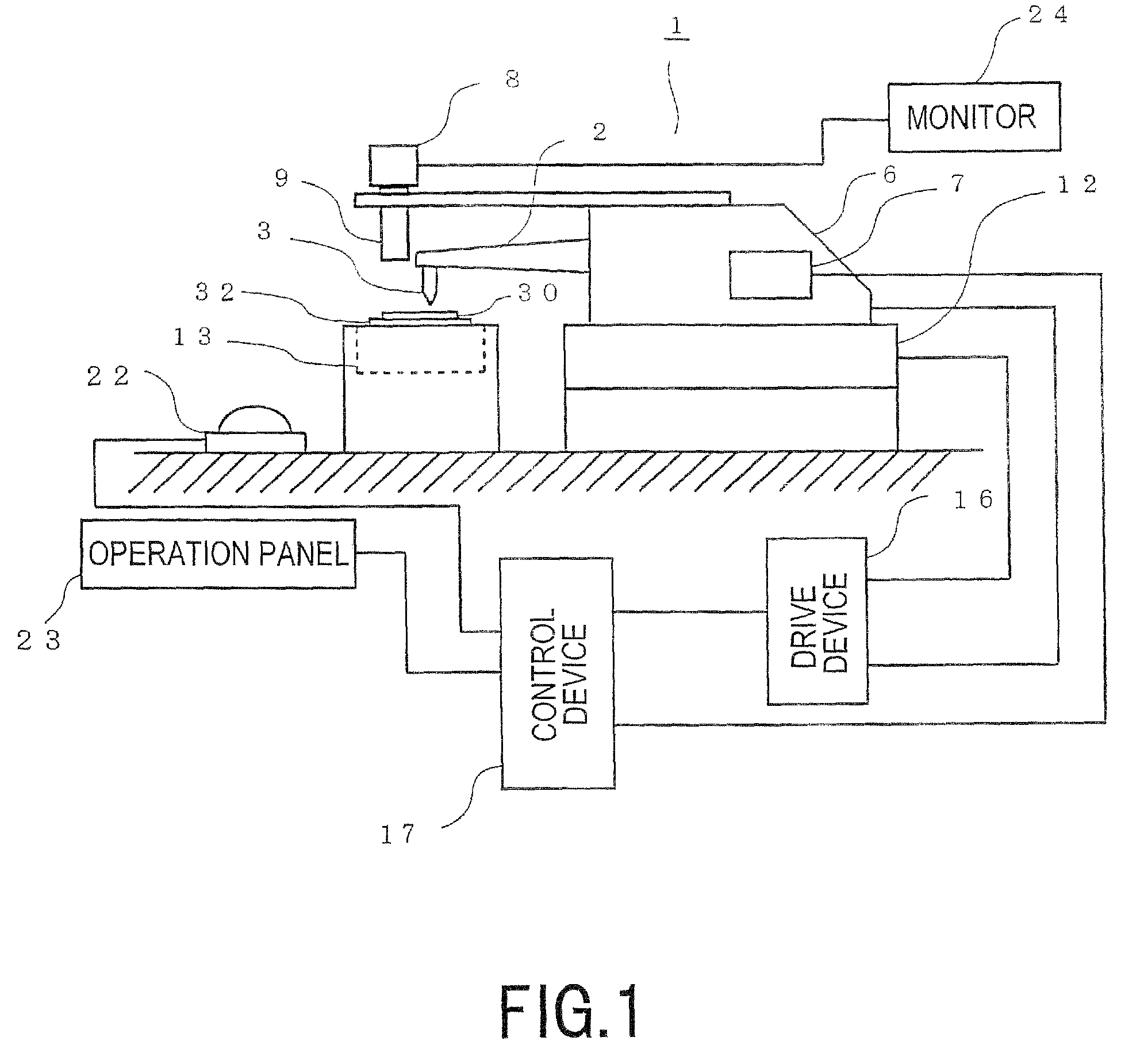
[0053]Referring now to FIG. 1 and FIG. 2, a configuration of a wire bonding. apparatus will be described. FIG. 1 is a block diagram showing a configuration of a wire bonding ap...


PUM

PropertyMeasurementUnit
diameteraaaaaaaaaa
diameteraaaaaaaaaa
diameter T4aaaaaaaaaa

Abstract

The invention provides a wire bonding method which enables formation of a low loop having a height not exceeding two times the wire diameter and secures sufficient pull strength of the wire even with the low loop shape. After having formed a contact-bonded ball at a first bonding point, a capillary moves upward and then toward a second bonding point to press a side surface of an upper portion of the contact-bonded ball, so that a protruded portion is formed on a top portion of the contact-bonded ball on the side of the second bonding point. After having formed the protruded portion of the contact-bonded ball, the capillary moves upward, and then downward while moving toward the second bonding point to press the protruded portion, so that a wire drawing portion for drawing the wire from the top portion of the contact-bonded ball horizontally is formed.

Description

BACKGROUND OF THE INVENTION[0001]1. Field of the Invention[0002]The present invention relates to a wire bonding method, a wire bonding apparatus, and a wire bonding control program for connecting a first bonding point and a second bonding point with a wire and, more specifically, to a wire bonding method, a wire bonding apparatus, and a wire bonding control program which are able to form a low loop.[0003]2. Description of the Related Art[0004]In a semiconductor device having a semiconductor chip integrated therein or in a substrate having the semiconductor chip mounted directly thereon, a lower-loop wire for connecting a pad and a lead of the semiconductor chip has been developed for reducing the thickness thereof.[0005]In JP-A-2004-172477, United States Unexamined Patent Publication No. 2007-284416, U.S. Pat. No. 7,347,352, and JP-A-2005-019778, lower-loop wires are disclosed.[0006]JP-A-2004-172477 includes a first step of connecting a wire to a first bonding point, a second step o...

Claims


Application Information

Patent Timeline
Patent Type & Authority Patents(United States)
IPC IPC(8): B23K31/02
CPCB23K20/007H01L24/48H01L24/78H01L24/85B23K2201/40H01L2224/85205H01L2224/45015H01L2924/01033H01L2924/01019H01L2924/01006H01L2924/14H01L2924/01082H01L2924/01079H01L2924/01047H01L2924/01015H01L2924/01005H01L2924/01004H01L2924/01002H01L2224/85181H01L2224/8503H01L2224/78303H01L2224/48599H01L24/45H01L2224/45144H01L2224/4809H01L2224/48095H01L2224/48465H01L2224/4847H01L2924/00014H01L2924/00012H01L2924/00H01L2924/20752B23K2101/40H01L2224/85399H01L2224/05599
Inventor ARAHATA, TORUISHII, SHINOBUFUJISAWA, HIROMI
Owner KAIJOO KK
Why Eureka
Try Eureka