
Circuits, systems, and methods for calibration of bias across a magneto-resistive sensor

a technology of magnetoresistive sensors and circuits, applied in the field of magnetic storage systems, can solve the problems of large extreme attention to noise and other errors, and complex implementation, and achieve the effect of fast and accurate calibration of bias

Active Publication Date: 2010-07-06
MARVELL ASIA PTE LTD
View PDF3 Cites 10 Cited by
  • Summary
  • Abstract
  • Description
  • Claims
  • Application Information

AI Technical Summary

Benefits of technology

[0021]The present invention advantageously provides for fast and accurate calibration of bias across an MR sensor that compensates for bias error introduced by the feedback path. These and other advantages of the present invention will become readily apparent from the detailed description of preferred embodiments below.

Problems solved by technology

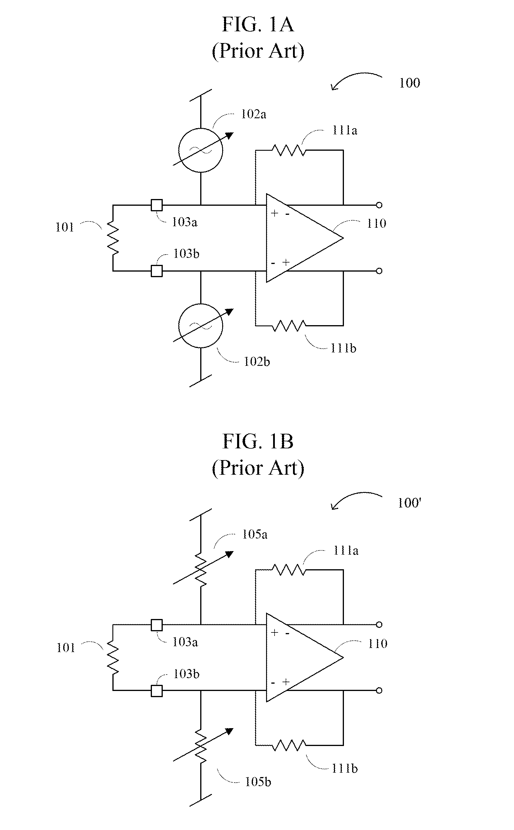
Due to the very weak signals detected by these read head sensors, extreme attention has to be paid to noise and other errors introduced by the preamplification system.
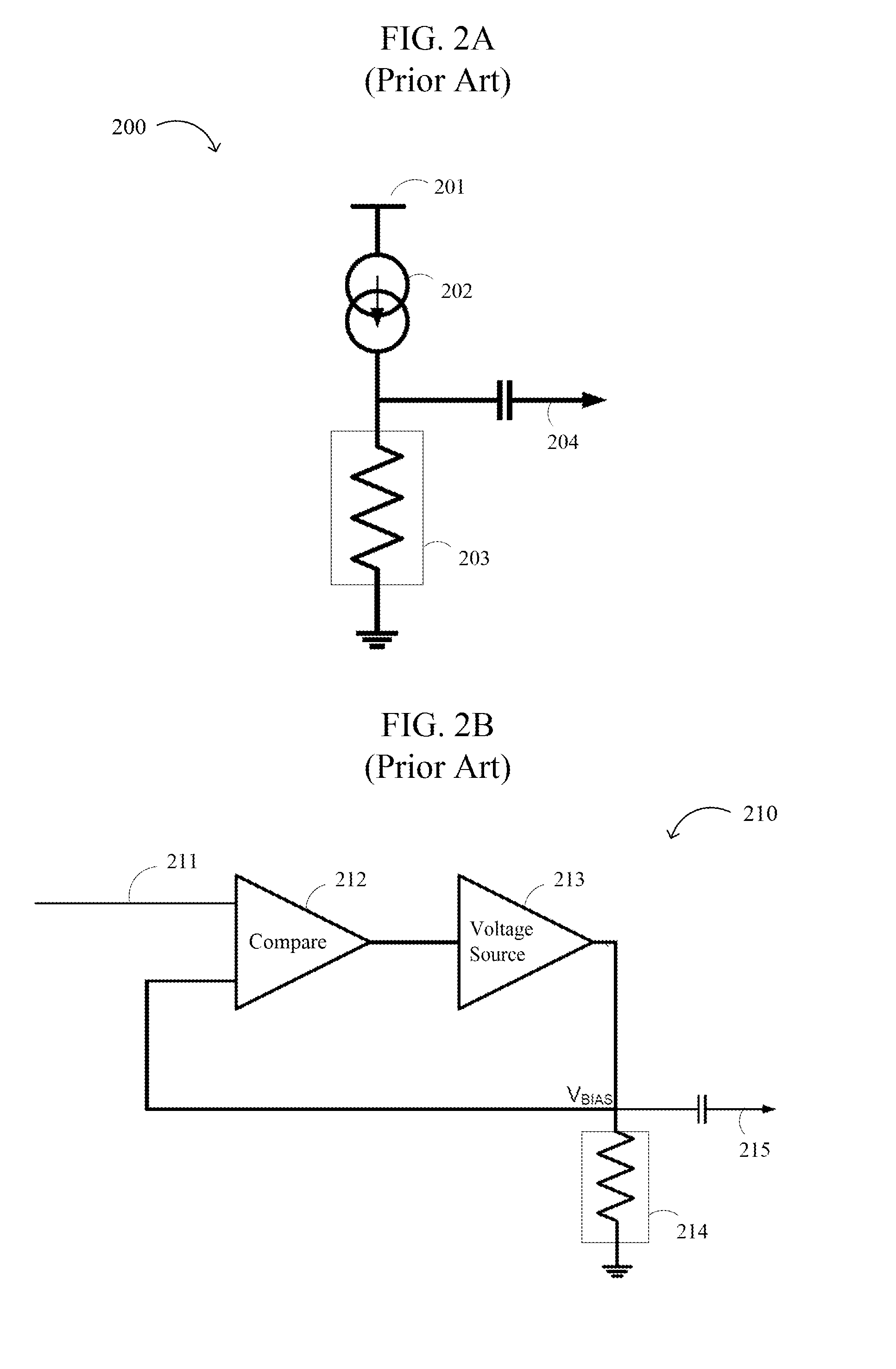
However, the voltage bias block generally produces larger bias noise than other biasing schemes, and requires a relatively complicated implementation.

Method used


Image

  • Circuits, systems, and methods for calibration of bias across a magneto-resistive sensor
  • Circuits, systems, and methods for calibration of bias across a magneto-resistive sensor
  • Circuits, systems, and methods for calibration of bias across a magneto-resistive sensor

Examples


Embodiment Construction

[0038]Reference will now be made in detail to the preferred embodiments of the invention, examples of which are illustrated in the accompanying drawings. While the invention will be described in conjunction with the preferred embodiments, it will be understood that they are not intended to limit the invention to these embodiments. On the contrary, the invention is intended to cover alternatives, modifications, and equivalents that may be included within the spirit and scope of the invention as defined by the appended claims. Furthermore, in the following detailed description of the present invention, numerous specific details are set forth in order to provide a thorough understanding of the present invention. However, it will be readily apparent to one skilled in the art that the present invention may be practiced without these specific details. In other instances, well-known methods, procedures, components, and circuits have not been described in detail so as not to unnecessarily o...


PUM

PropertyMeasurementUnit
voltageaaaaaaaaaa
bias voltageaaaaaaaaaa
currentaaaaaaaaaa

Abstract

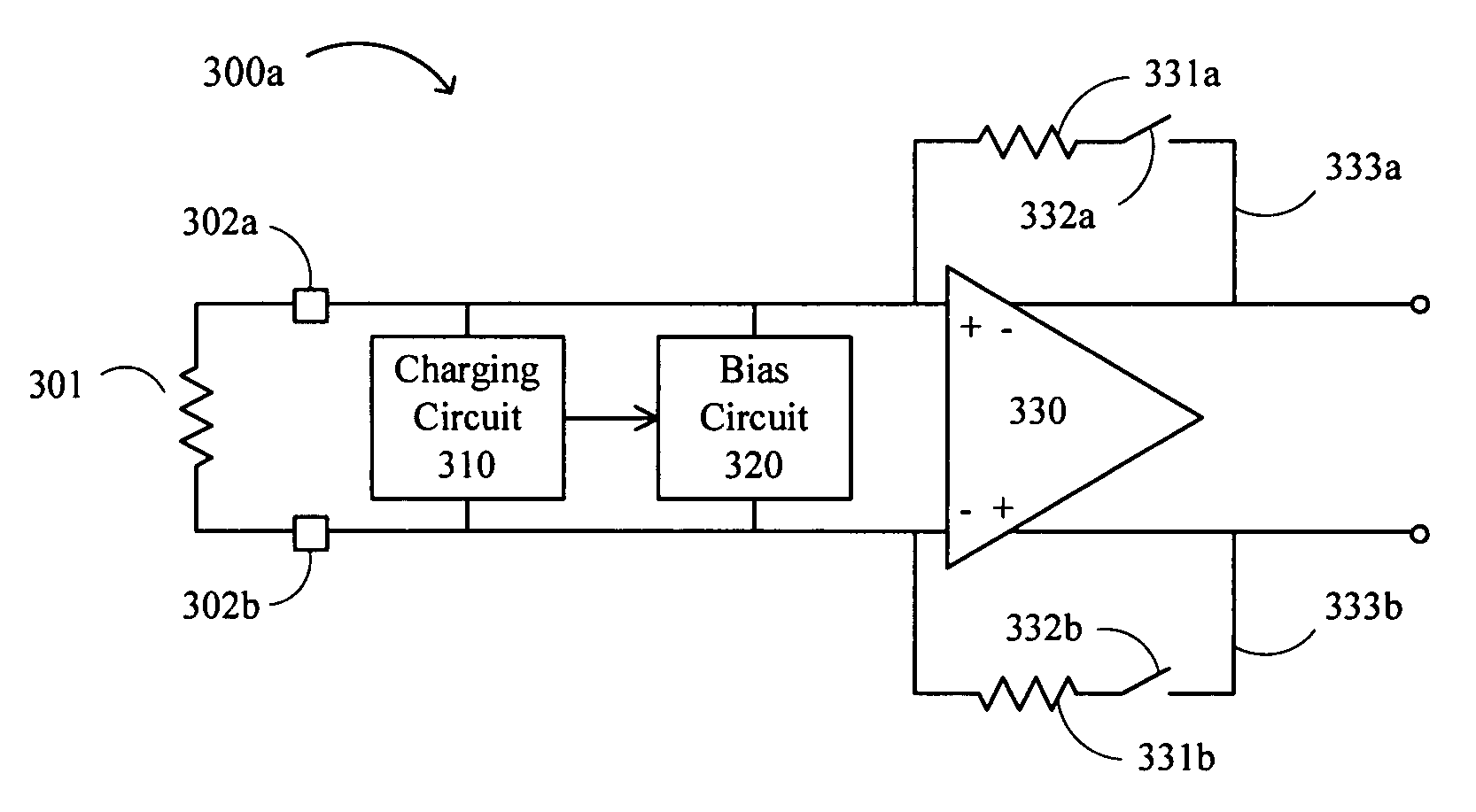
Circuits, systems, and methods for generating and calibrating bias for a magneto-resistive (MR) sensor. The circuit relates to a preamplifier circuit in a magnetic storage system, including an amplifier having an input coupled to a first MR sensor node, a first feedback path comprising a feedback resistor, the path configured to receive an amplifier output from the amplifier and to provide a feedback output to the first MR sensor node, a charging circuit configured to generate a current, apply the current to the first MR sensor node, and sample a voltage between the first MR sensor node and a second MR sensor node to produce a sampled voltage, the charging circuit operating when the feedback path is activated, and a bias circuit configured to apply a bias voltage across the first and second MR sensor nodes and to adjust the bias voltage to match the sampled voltage, the bias circuit operating when the feedback path is deactivated. The present invention advantageously provides for fast and accurate calibration of bias across an MR sensor that compensates for bias error introduced by the feedback path.

Description

RELATED APPLICATIONS[0001]This application claims the benefit of U.S. Provisional Application No. 60 / 822,690, filed Aug. 17, 2006, and U.S. Provisional Application No. 60 / 826,098, filed Sep. 19, 2006, each of which is incorporated herein by reference.FIELD OF THE INVENTION[0002]The present invention generally relates to the field of magnetic storage systems. More specifically, embodiments of the present invention pertain to circuits, systems, and methods for fast and accurate generation of bias across magneto-resistive (MR) sensors.DISCUSSION OF THE BACKGROUND[0003]Magnetic storage systems, such as hard disk drives (HDDs), are used as mass storage in a wide variety of devices, including but not limited to personal computers, digital versatile disc (DVD) players, high definition television (HDTV) receivers, vehicle control systems, cellular or mobile telephones, television set top boxes, and portable media players. As these magnetic storage systems become smaller and / or attain higher...

Claims


Application Information

Patent Timeline
Patent Type & Authority Patents(United States)
IPC IPC(8): G11B5/03
CPCG11B5/02G11B5/3948
Inventor VOO, THART FAH
Owner MARVELL ASIA PTE LTD
Learn More