Microphone with narrow directivity

a directivity and microphone technology, applied in the direction of electrical transducers, piezoelectric/electrostrictive transducers, transducer types, etc., can solve the problems of high wind noise level, and increasing the mass of air in the acoustic tube, so as to prevent the degradation of sound quality and efficiently reduce wind noise

Inactive Publication Date: 2010-07-06
AUDIO-TECHNICA
View PDF6 Cites 20 Cited by
  • Summary
  • Abstract
  • Description
  • Claims
  • Application Information

AI Technical Summary

Benefits of technology

[0015]The present invention has been developed in order to solve the problems of the conventional microphone with narrow directivity described above and an object thereof is to provide a microphone with narrow directivity capable of obtaining high directivity and reducing wind noise.
[0019]The film that covers the front acoustic terminal acts as a diaphragm and allows a high frequency sound wave to pass but not a low frequency sound wave because of its stiffness. Further, the above-mentioned film is capable of preventing an air flow from entering or going out by wind. Therefore, it is possible to prevent degradation in sound quality due to wind noise and an unpleasant feeling due to wind noise without the microphone's picking up wind noise. If a film made of vinyl chloride and formed into a corrugated shape is used, it is possible to more efficiently reduce wind noise.

Problems solved by technology

As is seen from FIG. 8, there is a drawback that the wind noise level is high and an unpleasant low frequency noise is likely to mix in.
On the other hand, a vibration noise of a microphone with narrow directivity depends on the mass of air in the acoustic tube, and the longer the acoustic tube, the more the mass of the air in the acoustic tube increases, thereby increasing the vibration noise as well.
However, there is a drawback that when an air flow hits the acoustic terminal 22 at the front end of the acoustic tube 10, low frequency wind noise is produced and unpleasant “gurgling” noise is output because the level of the frequency region of the wind noise is large.
However, if a low cut circuit is used, the diaphragm of the microphone unit vibrates at a low frequency due to wind, therefore, it is difficult to avoid sound modulated with a low frequency from being output.

Method used


Image

  • Microphone with narrow directivity
  • Microphone with narrow directivity
  • Microphone with narrow directivity

Examples


Embodiment Construction

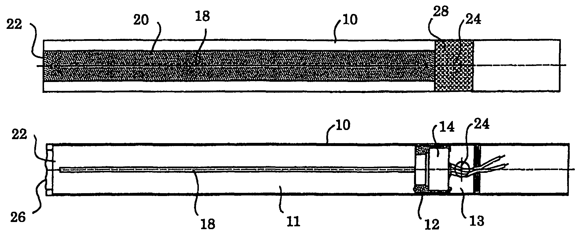
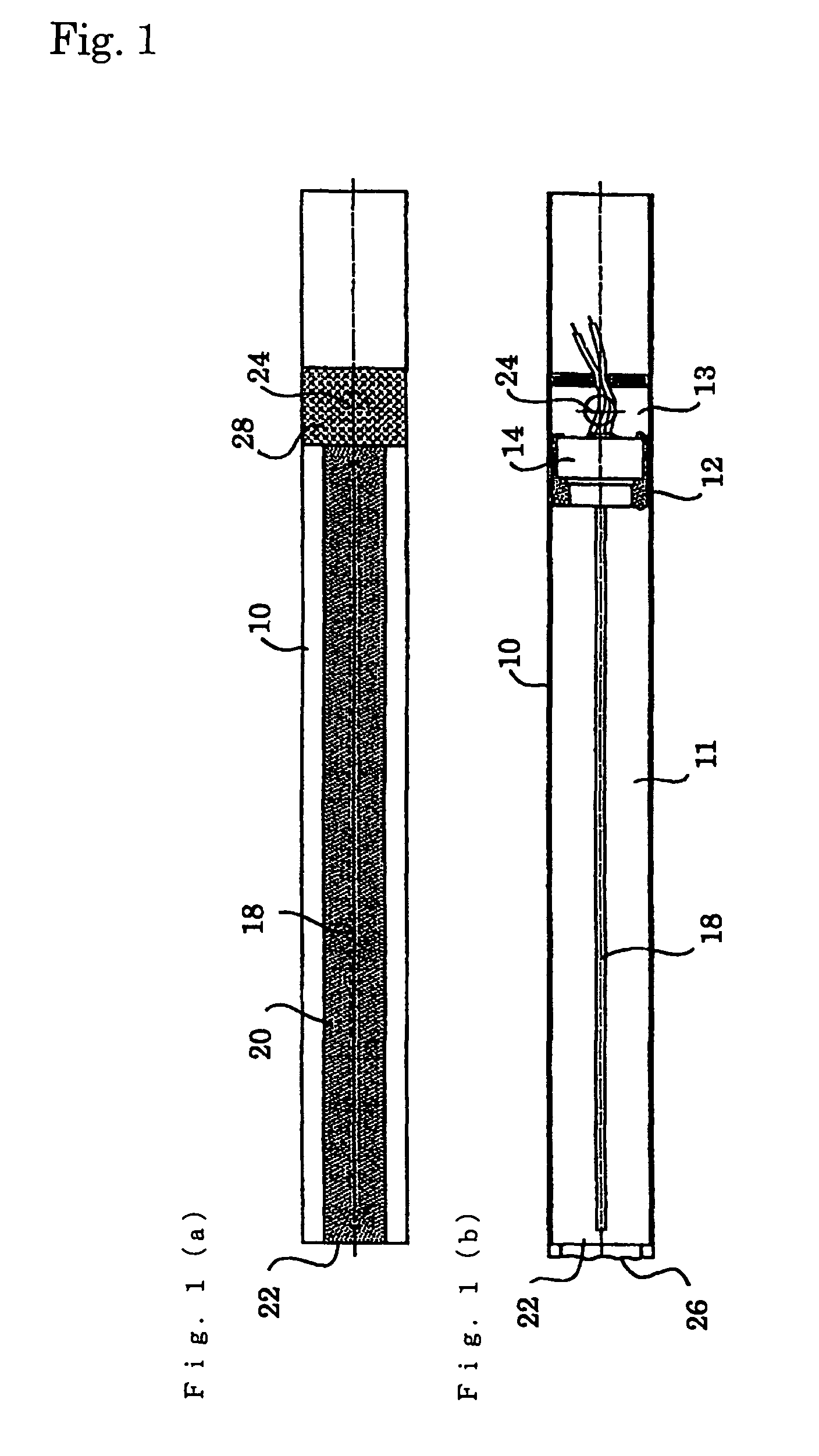
[0034]Embodiments of a microphone with narrow directivity according to the present invention are described below with reference to FIGS. 1(a) to 4. Here, the same symbols are attached to the same components as those in the configuration of the conventional example explained above.

[0035]In FIG. 1, symbol 10 denotes an acoustic tube made of an elongated cylindrical member. The acoustic tube 10 may be formed from a metal cylinder or a resin cylinder. The inside of the acoustic tube 10 is partitioned into a front acoustic chamber 11 and a rear acoustic chamber 13 by a unit holder 12 holding a microphone unit 14. The microphone unit 14 is arranged near the rear end (the right end in FIG. 1) of the acoustic tube 10 and the front acoustic chamber 11 is considerably longer than the rear acoustic chamber 13. The front end of the front acoustic chamber 11 is opened and comes to be a front acoustic terminal 22 for causing the front acoustic chamber 11 to communicate with an external space. In ...


PUM


Abstract

A microphone with narrow directivity capable of obtaining high directivity and reducing wind noise is obtained. A cylindrical acoustic tube, a microphone unit arranged in the acoustic tube, a front acoustic chamber and a rear acoustic chamber formed by partitioning the acoustic tube by the microphone unit, a front acoustic terminal for causing the front acoustic chamber to communicate with an external space, a rear acoustic terminal for causing the rear acoustic chamber to communicate with an external space, and a film that covers the front acoustic terminal are comprised. It is recommended that the rear acoustic terminal be also covered with a film. Further, it is recommended that the films be made of vinyl chloride and formed into a corrugated shape.

Description

BACKGROUND OF THE INVENTION[0001]1. Field of the Invention[0002]The present invention relates to a microphone with narrow directivity capable of efficiently reducing wind noise.[0003]2. Related Background of the Invention[0004]Conventionally, a general configuration for causing a microphone to have narrow directivity is a configuration using an acoustic tube. For example, such a configuration is used widely, in which the front end of an acoustic tube composed of a metal tube is used as an acoustic terminal and an opening provided in the circumferential wall of the acoustic tube is used as an acoustic resistor. Further, such a configuration is also used, in which an acoustic resistor is adhered to the opening. FIG. 5 shows an example of a conventional microphone with narrow directivity.[0005]In FIG. 5, to one end (the right end in the figure) portion of a cylindrical acoustic tube 10, a microphone unit 14 is attached, and the other end portion of the acoustic tube 10 is an acoustic t...

Claims


Application Information

Patent Timeline
Patent Type & Authority Patents(United States)
IPC IPC(8): H04R25/00
CPCH04R1/342H04R2410/07
Inventor AKINO, HIROSHI
Owner AUDIO-TECHNICA
Why Eureka
Try Eureka