Air recirculation system for stationary store rooms and for cargo spaces of refrigeration ships with high-bay racks

a technology of air recirculation system and stationary store room, which is applied in the direction of tank vessel, shaping tools, tank cleaning, etc., can solve the problems of difficult control of high-bay racks on board ships, in particular for the transportation of fruits, and achieve the effect of reducing the number of aeration

Inactive Publication Date: 2010-07-13
BECKER MARINE SYST
View PDF6 Cites 6 Cited by
  • Summary
  • Abstract
  • Description
  • Claims
  • Application Information

AI Technical Summary

Benefits of technology

[0007]Accordingly, the air recirculation system according to the invention consists in that two superimposed air circuits are configured in the store room or in the cargo space of a refrigeration ship in the area of every rack module, whereby at least one rack module, preferably two rack modules, are placed in the cargo space and whereby a shaft for the rack stacker is assigned to each rack module or a shaft for the rack stacker is placed between the two rack modules, whereby the shaft serves a common pressure distribution chamber of the inlet air for each rack module.
[0008]Accordingly, the high-bay rack store space in a store room or on board ships is characterized in that there is a shaft for the rack stacker in front of each rack module and that it must be kept free. This shaft is used for the air recirculation system as air distribution shaft.
[0009]The air conduction system according to the invention consequently consists in two air circuits placed above each other. Each of these air circuits passes through an air cooler by means of the power of fans which are fixed on the opposed side of the shaft of the rack module.
[0010]Further advantageous configurations of the invention are the subject of the subclaims.
[0011]Thus, the junction of the two superimposed air circuits ends in front of the inlet side of the air coolers placed above each other. Each of the air circuits passes through an air cooler by means of the power of fans which are fixed on the opposed side of the shaft in front of the rack module.
[0012]The air conduction is such that for the upper air circuits the air coolers are flown through vertically upwards, whereby the air is guided into the shaft by a cover duct. The bottom walls of this cover duct are provided with air outlet openings so that a direct impact takes place onto the upper areas of the goods to be loaded or onto the pallets.
[0012]The air conduction is such that for the upper air circuits the air coolers are flown through vertically upwards, whereby the air is guided into the shaft by a cover duct. The bottom walls of this cover duct are provided with air outlet openings so that a direct impact takes place onto the upper areas of the goods to be loaded or onto the pallets.
[0014]For the cooling of the outer walls of the store room or of the cargo space, the air ducts of the air circuits which are turned to the air coolers are configured in such a manner that part of the cold air is derived off for cooling the outer walls of the store room or of the cargo space.
[0015]Accordingly, in the air recirculation system according to the invention the air conduction is configured in such a manner that for the upper circuits the air coolers are flown through vertically upwards and the air is guided over the cover duct into the staple shaft. In the lower air circuit, the air is guided through the air coolers by the fans vertically from top to bottom and guided through a duct to the staple shaft as well.
[0016]With such an air recirculation system configured according to the invention, it is guaranteed that the high-bay rack warehouse as well as the store room or the cargo space are uniformly flushed with cooling air by maintaining constant predetermined temperatures so that the cargo is sufficiently cooled in all the layers.
[0017]Furthermore, the invention comprises a stationary store room or a cargo space of refrigeration ships with at least one high-bay rack, whereby the store room or cargo space is provided with an air recirculation system with the characteristics of claims 1 to 10.

Problems solved by technology

Because of their construction, high-bay racks on board of ships, in particular for the transport of fruit, are much more difficult to aerate in a controlled manner.

Method used


Image

  • Air recirculation system for stationary store rooms and for cargo spaces of refrigeration ships with high-bay racks
  • Air recirculation system for stationary store rooms and for cargo spaces of refrigeration ships with high-bay racks
  • Air recirculation system for stationary store rooms and for cargo spaces of refrigeration ships with high-bay racks

Examples


Embodiment Construction

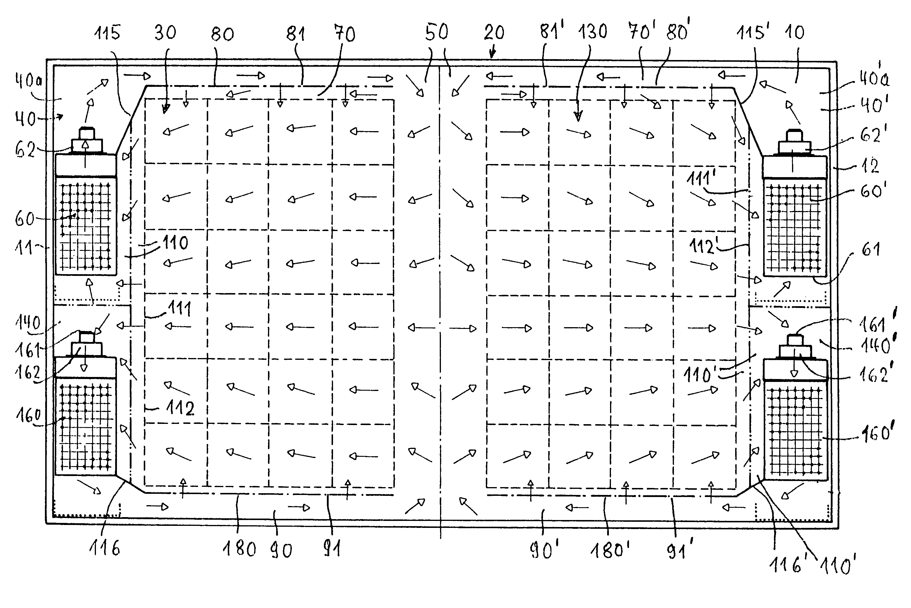
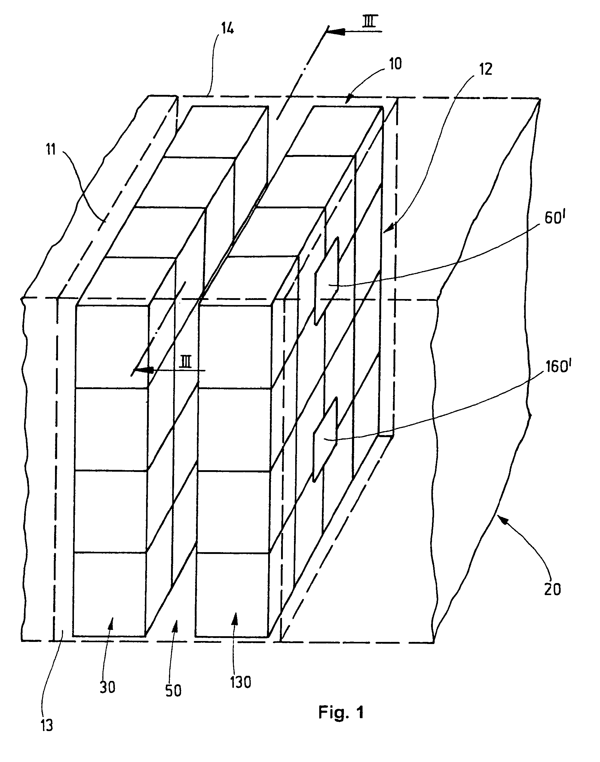
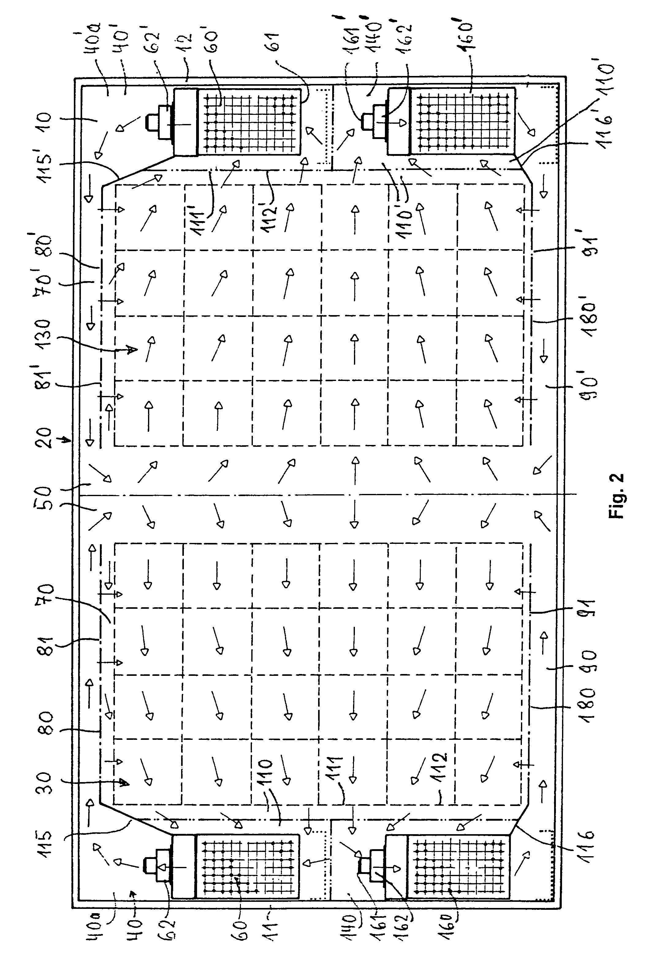
[0022]In FIGS. 1 and 2, 10 designates for example the cargo space of a refrigeration ship 20 with the side walls 11, 12 and the outer walls 21, 22. Two rack modules 30, 30 or high-bay racks are placed in the cargo space 10 which is enclosed on all sides by walls. A shaft 50 for rack stackers is configured between the two rack modules 30, 130. The rack modules 30, 130 receive preferably goods stacked on pallets P (FIG. 3).

[0023]Two superimposed air circuits 40, 140 and 40′, 140′ for cooling the cargo and the cargo space 10 are configured in the cargo space 10 in the area of each rack module 30, 130. The shaft 50 for the rack stacker is placed in front of each rack module 30, 30 or between the two rack modules 30, 130 placed the one besides the other. This shaft 50 serves as common pressure distribution chamber for the inlet air for each rack module 30, 130.

[0024]The junction of both superimposed air circuits 40, 140 or 40′, 140′ takes place in front of the inlet sides 61, 161 or 61′,...


PUM


Abstract

In order to flush with cooling air the goods stacked or palletized in a high-bay rack placed in a stationary store room or in the cargo space of a refrigeration ship by maintaining a constant cooling temperature in all the layers, an air recirculation system is proposed for which two superimposed air circuits (40, 140; 40′, 140′) are configured in the area of every rack module (30; 130), whereby at least one rack module, preferably two rack modules (30; 130), are placed in the cargo space and whereby a shaft (50) for the rack stacker is assigned to each rack module (30; 130) or a shaft (50) for the rack stacker is placed between the two rack modules (30; 130) placed the one besides the other, whereby the shaft (50) serves a common pressure distribution chamber of the inlet air for each rack module (30; 130).

Description

FIELD OF APPLICATION[0001]This invention relates to an air recirculation system for stationary store rooms and for cargo spaces of refrigeration ships with high-bay racks for stacked or palletized goods.PRIOR ART[0002]Air recirculation systems in the cargo spaces of refrigeration ships have the aim to flush the cargo with cooled air and thus the whole cargo space too.[0003]The quality conservation of the cargo during the transport determines an ambient temperature as constant as possible and a clean cargo space atmosphere. This is valid in particular for fruit freights. Here the air recirculation system should not only transfer the temperature but also take up the ripening warmth of the fruit and thus the development of maturity gas such as CO2, acetylene, ethylene etc. This presupposes again that the cargo is effectively sufficiently flushed with cooling air in all the layers.[0004]In the standard refrigeration ships, it is mostly reckoned with an air path through the cargo of appr...

Claims


Application Information

Patent Timeline
Patent Type & Authority Patents(United States)
IPC IPC(8): F25D17/06
CPCB63B57/04B21D37/08B21D37/04
Inventor LEHMANN, DIRKRODERMUND, SIEGMAR
Owner BECKER MARINE SYST
Why Eureka
Try Eureka