Video inspection system for inspection of rail components and method thereof

a video inspection system and rail component technology, applied in the direction of television system, television signal transmission by single/parallele channel, transportation and packaging, etc., can solve the problems of affecting the safety and reliability of rail transportation, significant property damage, and the derailment of the train traveling on the railroad track, so as to reduce time and effort, accurate and efficient inspection of rail components

Active Publication Date: 2010-07-13
ENSCO INC
View PDF10 Cites 93 Cited by
  • Summary
  • Abstract
  • Description
  • Claims
  • Application Information

AI Technical Summary

Benefits of technology

[0014]Another aspect of the present invention is in providing such a system and method that allows accurate and efficient inspection of rail components.
[0015]Yet another aspect of the present invention is in providing such a system and method that allows inspection of rail components with reduced time and effort.

Problems solved by technology

Conditions of the railroad track greatly impacts safety and reliability of rail transportation.
Failure or degradation of various rail components of a railroad track can cause derailment of the train traveling on the railroad track.
Such derailment can cause significant property damage, and injury to passengers and crew aboard the derailed train, as well as to bystanders.
However, the quality of the visual inspection is generally poor, especially when the visual inspection is performed from a hi-railer which is a vehicle that has been modified to drive on railroad tracks.
The limitation of this prior art method of inspecting railroad components is that it is very difficult for the inspector to see the small defects or damage in the railroad components while driving the hi-railer.
This limitation is especially exacerbated by the fact that defects or damage to joint bars are especially difficult to see since the joint bars are secured to the sides of the rails, and joint bars can fail due to cracks that are about one millimeter in width.
However, such inspection performed on foot is a very slow and tedious process requiring many hours to inspect several miles of railroad track.
The significant limitation of the inspection vehicle disclosed in Trosino et al. and the method taught therein is that it requires the inspector to continually perform visual inspection of the railroad track while traveling on the railroad track, such inspection being not much better in quality as compared to the conventional inspection method from a hi-railer noted above.
This is especially problematic if the damage and / or defect to the railroad track is very small and difficult for the inspector to see.
For example, as noted above, many derailment accidents are attributable to damage or failure of joint bars.
Due to the positioning of the joint bars adjacent to the web of the rail, surface cracks on the joint bars would be extremely difficult to see by the inspector utilizing the inspection vehicle described in Trosino et al.
Therefore, whereas the railcar vehicle of Trosino et al. is appropriate for inspecting a railroad track for large anomalies which are easily visible to the inspector, such as the presence of weeds, blocked drain, etc., the described inspection vehicle does not allow facilitated inspection of smaller rail components, or smaller defects associated thereto.
Therefore, in view of the above, there exists an unfulfilled need for a system for inspecting rail components of a railroad track, and a method thereof.
In particular, there exists an unfulfilled need for such a system and method that allows accurate and efficient, inspection of rail components, even for very small defects or damage, with reduced time and effort.

Method used


Image

  • Video inspection system for inspection of rail components and method thereof
  • Video inspection system for inspection of rail components and method thereof
  • Video inspection system for inspection of rail components and method thereof

Examples


Embodiment Construction

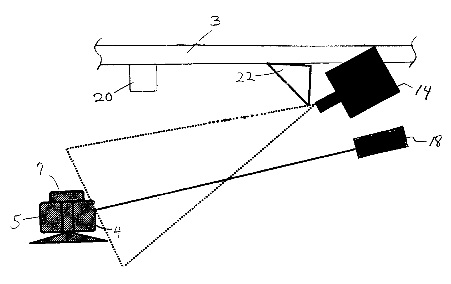
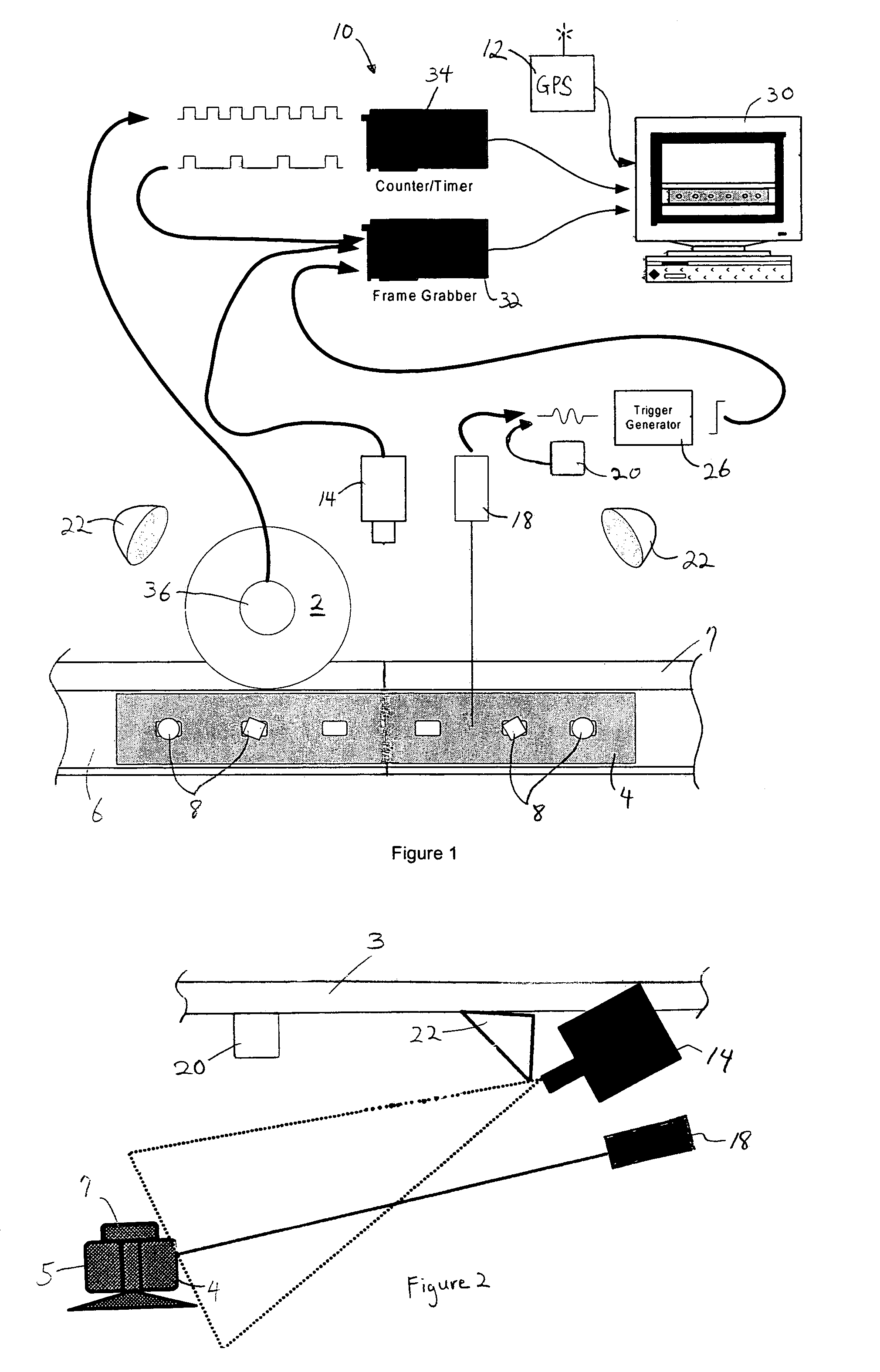
[0040]FIG. 1 shows an illustration of a video inspection system 10 in accordance with one example embodiment of the present invention that facilitates inspection of rail components while traveling on the railroad track. In particular, as will be evident from the discussion below, the video inspection system 10 facilitates inspection of rail components such as joint bars, switch frogs, rail fasteners, switch points, and rails themselves.

[0041]In the schematic example of FIG. 1, the inspected rail component is a joint bar 4 that secures the sides (i.e. webs) of two rails 6 and 7 of a railroad track together via fasteners 8. As can be appreciated, only one side of the railroad track is shown in FIG. 1. As will be discussed below, the video inspection system 10 utilizes digital video, computer imaging, and illumination technologies to allow accurate, and efficient inspection of rail components, with reduced time and effort as compared to conventional methods of inspection. It should be ...


PUM


Abstract

A video inspection system and method for facilitating inspection of a rail component while traveling on the railroad track. The system includes a light source that provides illumination to a rail of the railroad track, a triggering device for automatically providing a trigger signal, a camera adapted to provide an image of the illuminated rail component, and a computing device adapted to capture the image provided by the camera based on the trigger signal. A method for inspecting rail components is also provided, the method including the steps of illuminating a rail of the railroad track, automatically providing a trigger signal, providing a camera adapted to provide an image of the rail component, and capturing the image of the rail component that is provided by the camera based on the trigger signal.

Description

[0001]This application claims priority to U.S. Provisional Application No. 60 / 467,150, filed May 2, 2003, the contents of which are incorporated herein by reference.BACKGROUND[0002]1. Field of the Invention[0003]The present invention is directed to a system for inspecting rail components of a railroad track, and a method for inspecting such rail components.[0004]2. Description of Related Art[0005]Maintaining proper conditions of rail components of a railroad track is of paramount importance in the railroad transportation industry. Rail components include joint bars, fasteners, switch frogs, rail fasteners, etc. as well as the rail segments themselves which form the railroad track. Conditions of the railroad track greatly impacts safety and reliability of rail transportation. Failure or degradation of various rail components of a railroad track can cause derailment of the train traveling on the railroad track. Such derailment can cause significant property damage, and injury to passe...

Claims


Application Information

Patent Timeline
Patent Type & Authority Patents(United States)
IPC IPC(8): H04N7/12B61K9/08B61L23/04
CPCB61K9/08B61L23/042B61L23/044B61L23/045B61L2205/04
Inventor NEJIKOVSKY, BORISDIAZ, CHRISTIANCARR, GARY A.PARNIANI, TOOFAN
Owner ENSCO INC
Why Eureka
Try Eureka