Optical system for determining the angular position of a radiating point source and method of employing

an optical system and radiating point source technology, applied in the direction of direction finders using electromagnetic waves, using reradiation, direction finders, etc., can solve the problems that the prior art fails to teach or suggest the specific techniques employed by applicants to accurately measure angular position and distance, and achieve the effect of avoiding sensing and facilitating accurate phase measuremen

Active Publication Date: 2010-07-13
NORTHERN DIGITAL
View PDF9 Cites 33 Cited by
  • Summary
  • Abstract
  • Description
  • Claims
  • Application Information

AI Technical Summary

Benefits of technology

[0014](4) One example of a mask pattern contains three frequencies, including the fundamental frequency f0, f1=5*f0, f2=25*f0. The mask length is longer than the detector to ensure that the detector is fully covered by the pattern for all source positions. The phase determination of each of the frequency components allows resolving to finer and finer degrees as with a vernier caliper.
[0024](11) A unique aspect of the present invention is that it permits parallel image processing of a relatively low number of channels. As such, signal modulation can be employed to reduce the susceptibility to optical or electromagnetic interference. This is a particularly important attribute in severe environments such as are found in jet cockpits where the full sun interference causes problems with conventional optical systems. In the preferred embodiment of the present invention, modulation of 100 Khz is employed so that the system can operate even when facing the sun.
[0030]It is a further object of the present invention to provide such a system in which three mask transmission frequencies are identified and provide coarse and fine measurement.
[0031]It is a still further object of the present invention to provide such a system in which sufficient sample points are employed to facilitate accurate measurement of phase while avoiding the sensing of other image frequencies.

Problems solved by technology

In the prior art, this general concept is well known, however, the prior art fails to teach or suggest the specific techniques employed by Applicant to accurately measure angular position and distance using such a structure.

Method used


Image

  • Optical system for determining the angular position of a radiating point source and method of employing
  • Optical system for determining the angular position of a radiating point source and method of employing
  • Optical system for determining the angular position of a radiating point source and method of employing

Examples


Embodiment Construction

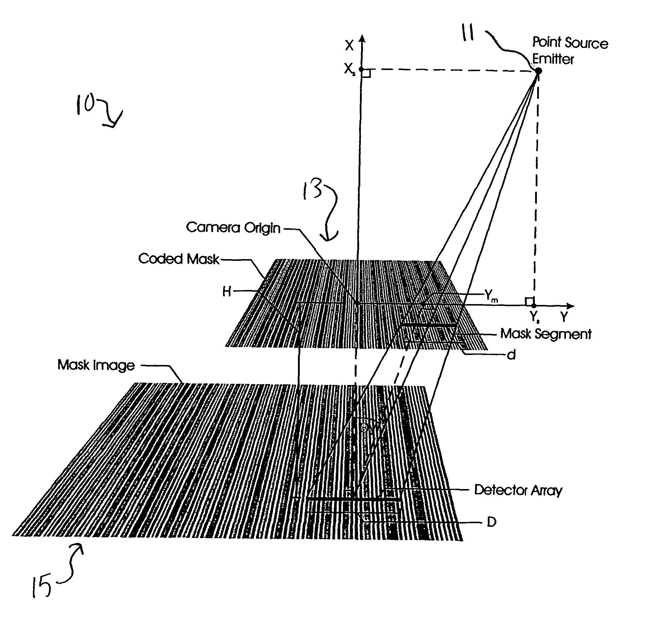
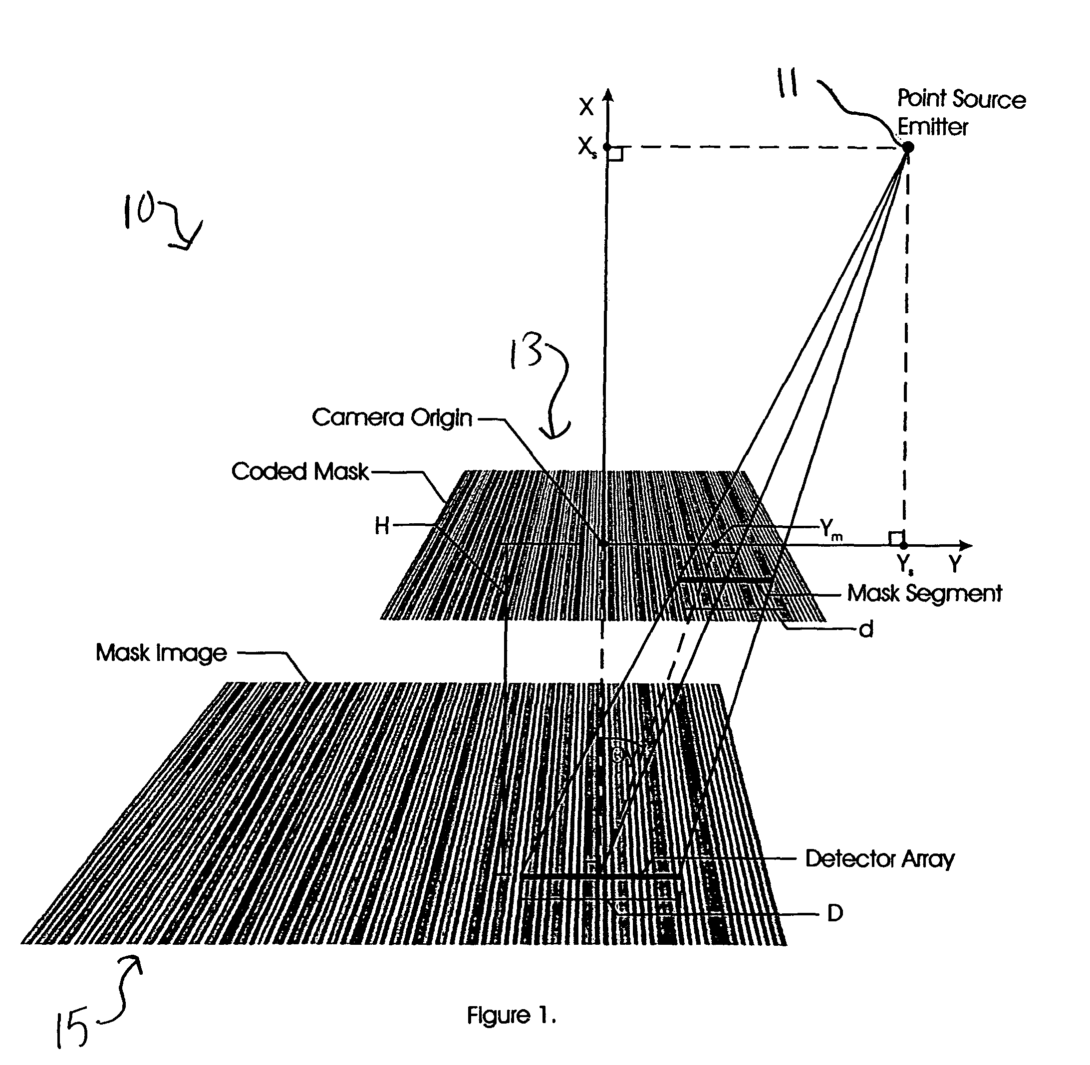
[0054]A first embodiment of the present invention is disclosed in detail with reference to FIGS. 1-11. A primary aspect of the first embodiment 10 of the present invention describes a method for determining the angular position of a point source of radiation 11 with respect to a detector 15 by examining the phases of periodic components of the projected image of a variable transmissivity mask 13. The preferred embodiment encodes the transmissivity mask with several frequencies that have logarithmic separations and measures the phases of said frequencies received by the detector.

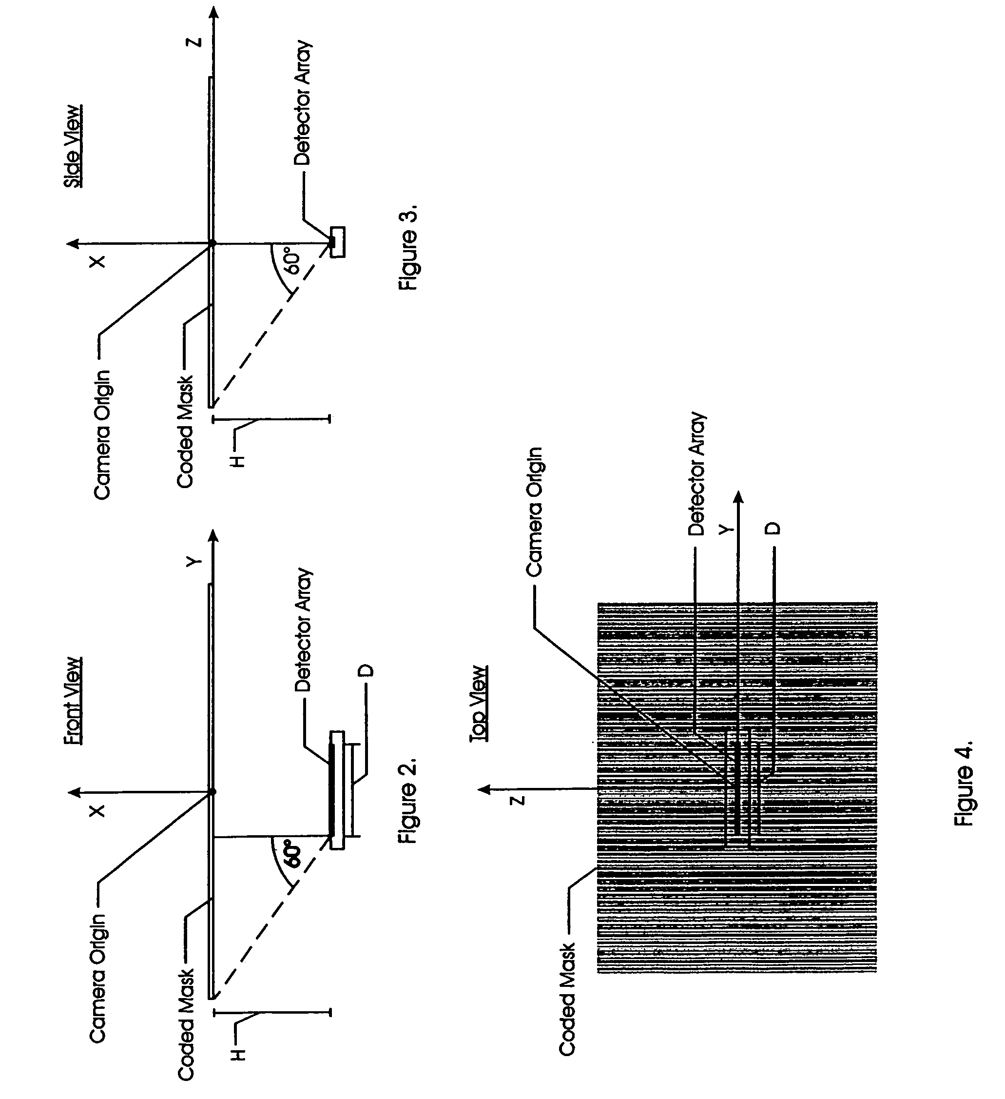
[0055]With reference to FIGS. 1-4, the configuration of the system used to practice the method is seen.

[0056]The mask image fundamental period (1 / f0) is made about 1.2% smaller than the detector length (D) to allow for 1.2% magnification at the nominal operating distance of 0.5 meter. FIG. 5 shows a graphical representation of the constituent mask frequencies f0, 5f0, and 25f0, as well as a graph of the compo...


PUM


Abstract

An optical system for determining the angular position of a radiating point source is disclosed, wherein radiation from a point source travels through a mask and onto the surface of a sensor. A preferred embodiment employs a plurality of mask transmission frequencies and a detector designed to be sensitive to the phases of the frequencies. A computer measures the phases of a plurality of detected image frequencies. Measurement of the particular phases of the frequency components allows determination of the image shift on the detector axis. The image shift is then used to compute angle of incidence of the light source upon the detector. The preferred embodiment employs a refractive window, hence the angle of incidence between point radiating source and mask are determined using the window index of refraction and refraction equations. Applications include within the cockpit of a jet aircraft.

Description

[0001]This application is a continuation-in-part of application Ser. No. 10 / 073,335, filed on Feb. 13, 2002 now U.S. Pat. No. 7,027,634.BACKGROUND OF THE INVENTION[0002]The present invention relates to methods of employing an optical system for determining the angular position of a radiating point source as well as the system itself. The disclosure of the parent application identified above is hereby incorporated by reference herein. In the present invention, radiation from a point source travels through a mask and onto the surface of a sensor. In the prior art, this general concept is well known, however, the prior art fails to teach or suggest the specific techniques employed by Applicant to accurately measure angular position and distance using such a structure.[0003]Prior art systems have used masked or coded apertures placed above multi-element detectors. All of these techniques have attempted to determine the position of a projected pattern on a detector surface by comparing s...

Claims


Application Information

Patent Timeline
Patent Type & Authority Patents(United States)
IPC IPC(8): G06K9/00G01B11/26G01S3/783G01S5/16G01S11/12
CPCG01B11/26G01S3/7835G01S5/16G01S11/12
Inventor ODELL, DON
Owner NORTHERN DIGITAL
Why Eureka
Try Eureka