Hydraulic lift for top of mobile living quarters

a mobile living quarters and hydraulic lift technology, applied in the directions of transportation and packaging, loading/unloading vehicle arrangment, transportation items, etc., can solve the problems of user having to readjust the valves, excessive wear, and user binds, so as to achieve the effect of evenly lowering the top and lowering the top

Inactive Publication Date: 2010-07-20
STEURY MATHEW +1
View PDF33 Cites 10 Cited by
  • Summary
  • Abstract
  • Description
  • Claims
  • Application Information

AI Technical Summary

Benefits of technology

[0004]The present invention is a liftable top for mobile living quarters. The top is supported by lifting members which are a piston retained in a cylinder. The lifting members extend when receiving fluid and retract when fluid is discharged from the lifting members. Fluid is discharged at a rate which is a function of the weight borne by the lifting member. A pump communicates fluid to the lifting members through fluid lines. Each fluid line connected to the lifting members has a flow control valve therein. Each line a...

Problems solved by technology

If the posts do not descend evenly, binding and excessive wear can occur.
If a user guessed wrong in his adjustment of one or more of the posts, the camper could bind due to an uneven rate of descent.
Also, if the weight distri...

Method used


Image

  • Hydraulic lift for top of mobile living quarters
  • Hydraulic lift for top of mobile living quarters
  • Hydraulic lift for top of mobile living quarters

Examples


Embodiment Construction

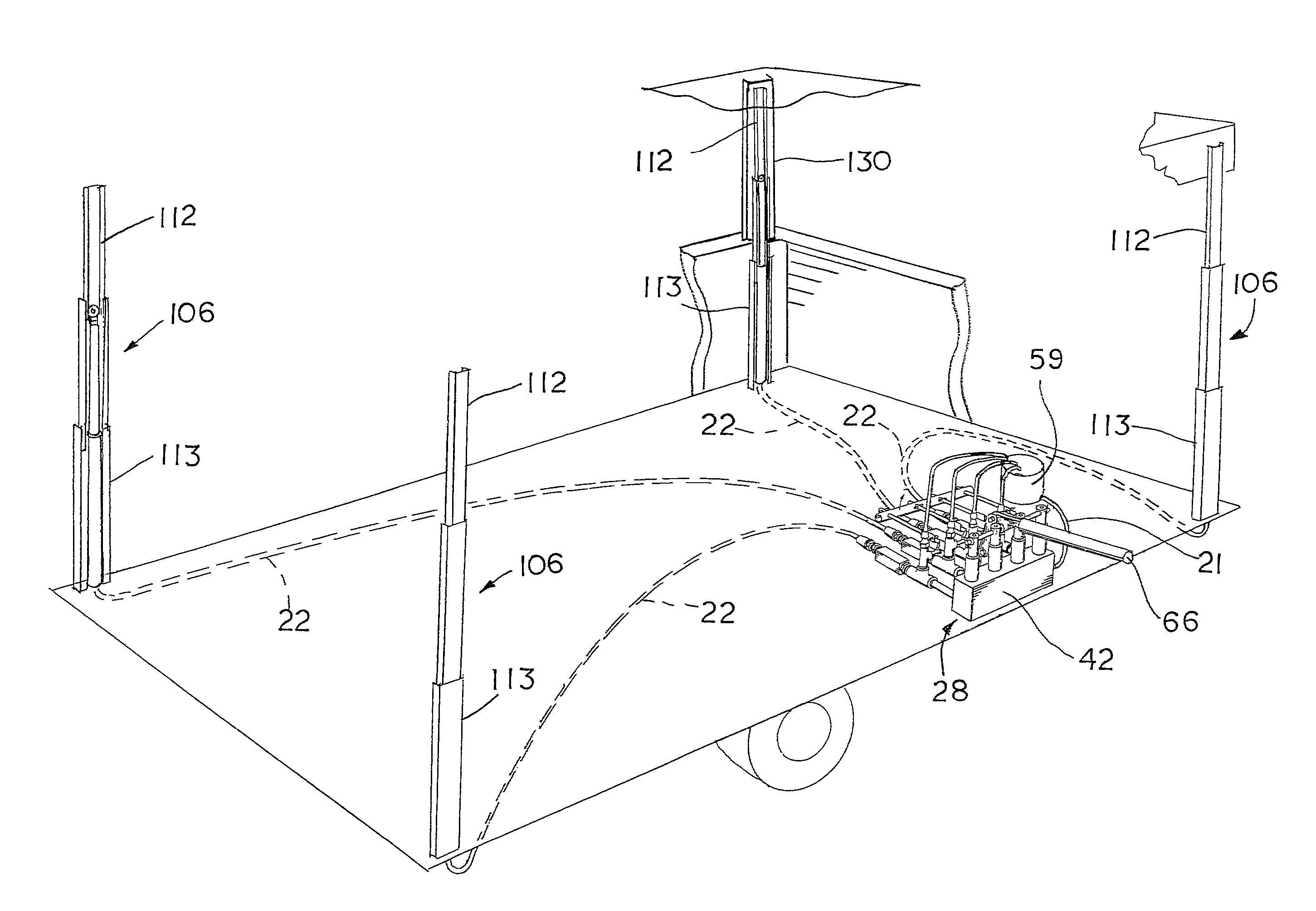
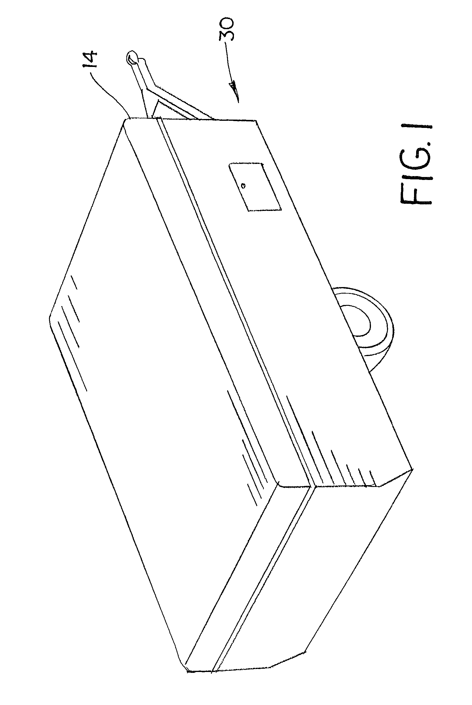
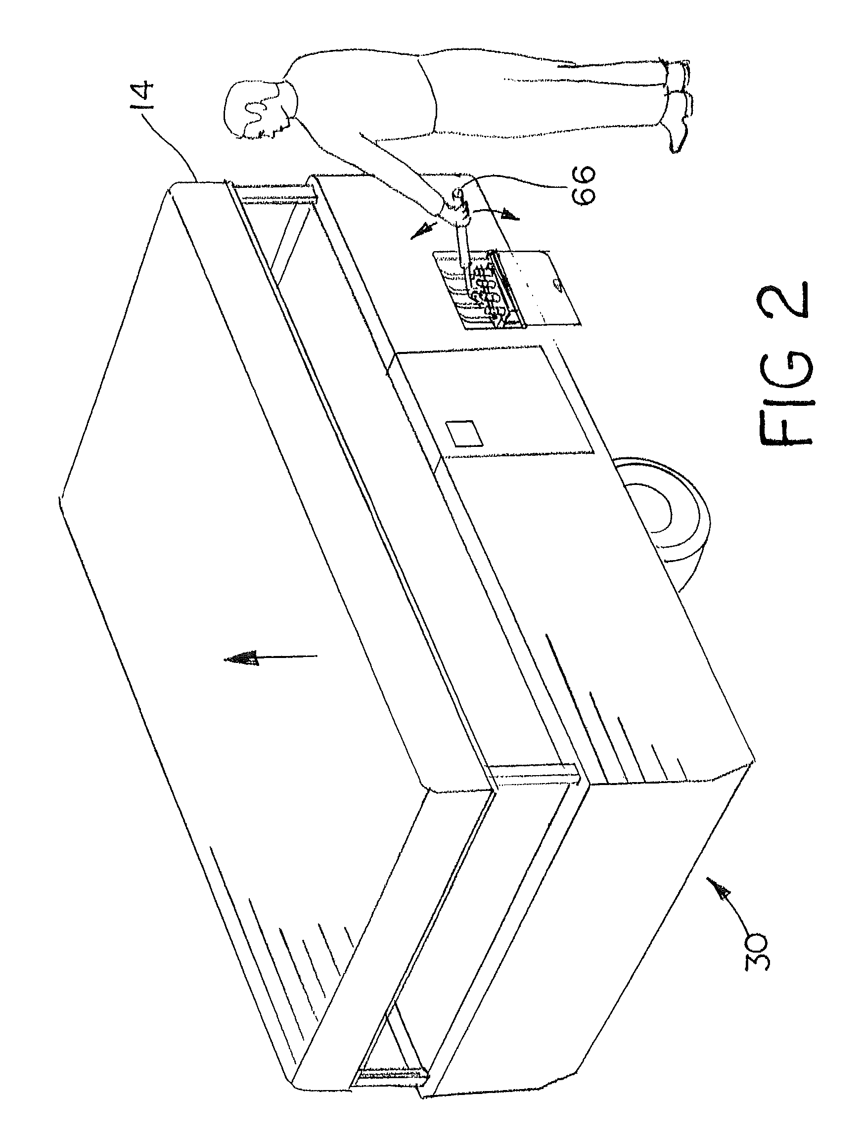
[0024]The hydraulic lift of this invention is used to lift a structure. This structure may be any structure that requires uniform lifting, as well as uniform and controlled descent. The embodiment detailed as follows, pertains to a camper 30, but may be used for boat lifts, work benches, tables, etc.

[0025]The hydraulic lift of this invention has four lifting members 12 that are placed near corners of a camper top 14. The lifting members 12 have a piston 16 and a cylinder 18. The piston 16 and cylinder 18 form a chamber 20 that receives fluid through a fluid line 22. The piston 16 may have a bore 4 running its entire length, as shown in FIG. 18, that is capped with a threaded plug 6. This allows bleeding of air form the chamber 20 when hydraulic fluid is used as the fluid. When the piston 16 has a bore 4, as shown in FIG. 18, the piston 16 is preferably a rod having the same diameter along its entire length. When fluid is forced into the chamber 20 through the fluid line 22 the lifti...


PUM


Abstract

A hydraulic lift for mobile living quarters having a liftable top. A fluid pressure source communicates fluid through fluid lines connected to a plurality of lifting members that extend upon receipt of fluid and retract upon discharging fluid. The rate at which fluid is discharged from the lifting members is a function of how much weight each lifting member bears. Each of the fluid lines has a flow control valve between the pressure source and each lifting member. Fluid is communicated through the flow control valve to the lifting member connected to the pressure source the fluid is also communicated through the flow control valve when fluid is discharged from the lifting member. The flow control valve limits the flow rate of the fluid to a constant predetermined rate when the fluid is discharged from the lifting member.

Description

CROSS REFERENCE TO RELATED APPLICATIONS[0001]This application claims the benefit and priority of U.S. Provisional Patent Application Ser. No. 60 / 806,677, filed Jul. 6, 2006, the subject matter of which is hereby incorporated by reference.BACKGROUND OF THE INVENTION[0002]Camping trailers have long been provided with lift mechanisms for raising and lowering the top. Some lifts use telescoping corner posts to accomplish this task.[0003]U.S. Pat. No. 3,363,932 uses a single pumping piston which supplies four separate hydraulic cylinders in four corner posts and has adjustable valves to allow each of the corner posts to descend at an equal rate to the other posts. The valves restrict the flow of fluid returning from the hydraulic cylinders in the corner posts, which adjusts the rate of descent for the cylinder in line with the adjustable valve. If the posts do not descend evenly, binding and excessive wear can occur. In use the weight of the camper top would almost never be evenly distri...

Claims


Application Information

Patent Timeline
IPC IPC(8): B60P3/355
CPCB60P3/34
Inventor STEURY, MATHEWSTEURY, EDWIN
Owner STEURY MATHEW
Why Eureka
Try Eureka