Negative insert for cutting machining

a technology of inserts and cutting machining, which is applied in the direction of milling cutters, turning equipment, milling equipment, etc., can solve the problems of negative influence, increase the roughness of the generated surface, annoyance of noise, etc., and achieve excellent behaviour, reduce the roughness of the surface, and improve the properties of the insert

Active Publication Date: 2010-07-20
SECO TOOLS AB
View PDF14 Cites 19 Cited by
  • Summary
  • Abstract
  • Description
  • Claims
  • Application Information

AI Technical Summary

Benefits of technology

[0005]Furthermore, variations of reaction forces of a rotating work piece machined by such an insert will give rise to vibrations in the insert and work piece, which may produce annoying noise and also will have a negative influence upon the result of the turning operation, i.e., increase the roughness of the generated surface. Another effect of vibrations could be reduced tool life.
[0009]It has been found that such a chamfer extending the machining region of the insert during cutting machining operation to a surface results in a number of advantages with respect to negative inserts for cutting machining already known.
[0010]Vibrations of such an insert during cutting machining operation are remarkably reduced, especially in the tangential direction with respect to a work piece, which will rotate in the case of a turning insert. This results in an improved machining result, less wear upon the insert and less production of noise during the operation. The speed of the wear of the uppermost flank of the clearance side of the insert will also be reduced, so that a high accuracy machining may be carried out by the insert over a longer time within the tolerance range. Accordingly, need of adjustments in order to keep the accuracy at the machined work piece is reduced and the life time of the insert is prolonged, so that such inserts are not to be replaced as often as inserts already known.
[0015]According to another aspect of the invention the extension of the chamfer from the cutting edge to the clearance side is 0.03 mm-0.30 mm, 0.03 mm-0.20 mm, 0.04 mm-0.15 mm or 0.04 mm-0.08 mm. It has been found that a chamfer with an extension within these ranges will when applied substantially tangentially to a work piece to be machined enable efficient machining of the work piece thereby while achieving the advantages of less vibrations and reduced flank wear.
[0020]According to another aspect of the invention the insert is provided with a convex wiper edge at least at one corner thereof, the wiper being defined by at least one radius. It is known that such a wiper geometry will reduce the roughness of the surface of the work piece machined with respect to a standard insert geometry having a rounded corner with one radius, and the wiper geometry in connection with the chamfer will improve the properties of the insert according to the invention even more.
[0021]According to another aspect of the invention at least the portions thereof intended to be applied to a work piece to be machined are made of boron nitride (BN). Boron nitride has physical properties making it well suited as a material for especially turning inserts, and it has turned out that inserts of this material having a chamfer according to the above gives rise to an excellent behaviour when carrying out cutting machining, especially turning operations thereby. The boron nitride is then preferably cubic boron nitride (CBN), but poly crystalline boron nitride (PCBN) is also advantageous.

Problems solved by technology

Furthermore, variations of reaction forces of a rotating work piece machined by such an insert will give rise to vibrations in the insert and work piece, which may produce annoying noise and also will have a negative influence upon the result of the turning operation, i.e., increase the roughness of the generated surface.
Another effect of vibrations could be reduced tool life.

Method used


Image

  • Negative insert for cutting machining
  • Negative insert for cutting machining
  • Negative insert for cutting machining

Examples


Embodiment Construction

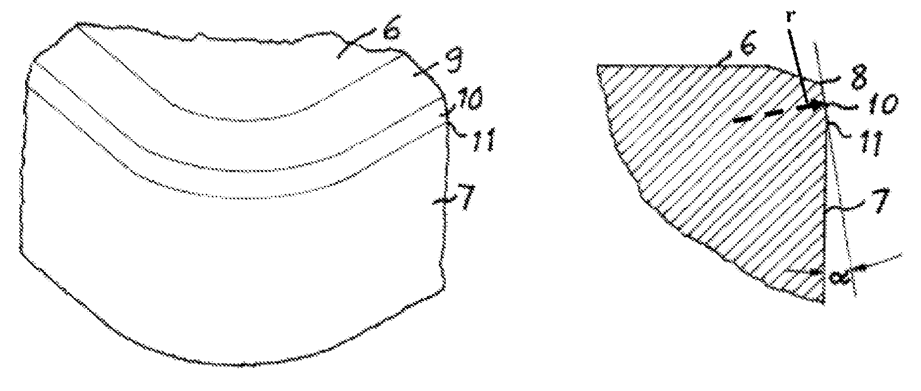
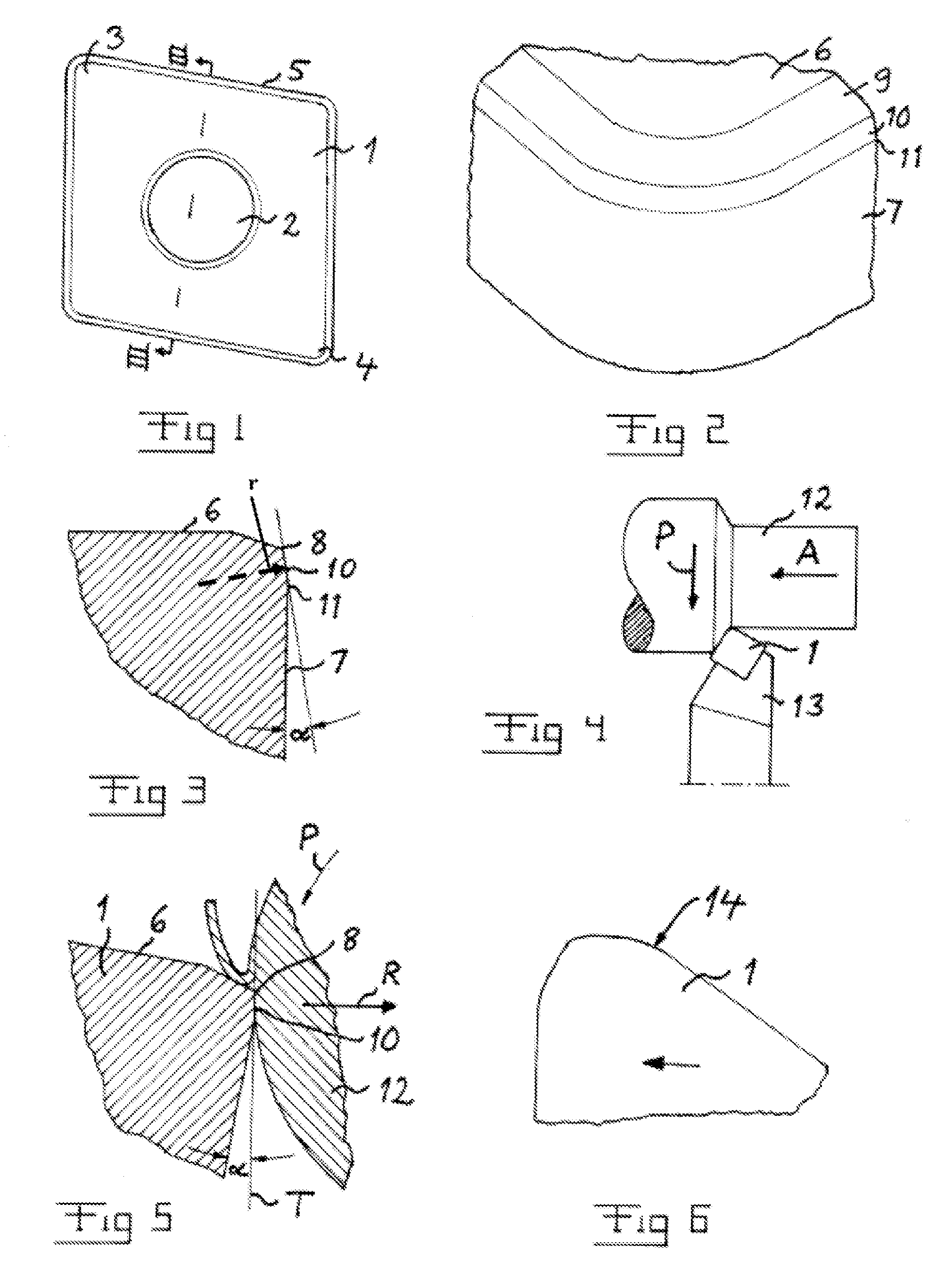
[0034]FIG. 1 shows a negative turning insert 1 having a geometry typical for such an insert, and which is adapted to be secured in a tool holder by appropriate means, such as tightening means, while using a recess 2 therein. Such a recess is not necessary, but the insert may be without a recess and held in the tool holder by a clamp. The insert will machine a work piece by the region of a corner thereof, and it is preferably of the type enabling such machining by use of more than one such corner, such as at least the corners 3 and 4, so that the position of the insert in the tool holder may be changed when the accuracy of the machining may not be guaranteed any longer when using a certain corner region for such machining. The dimensions of the lateral sides 5 of the insert are preferably so that adjacent corners may be used for machining, which means that the cutting depths may then not be larger than half the distance between such two adjacent corners, so that for instance for an i...


PUM

PropertyMeasurementUnit
radiusaaaaaaaaaa
angleaaaaaaaaaa
angleaaaaaaaaaa

Abstract

A negative insert for cutting machining has a top side, a clearance side perpendicular thereto and a cutting edge in a region interconnecting these sides and extending substantially in parallel with these sides. The insert has further a flat or rounded chamfer connecting the cutting edge to the clearance side on at least one lateral side of the insert in the region of a corner thereof. The chamfer makes an angle of 1°-15° with the clearance side for enabling application of the chamfer substantially tangentially to a work piece to be machined for bearing of the insert in two dimensions against the work piece during cutting machining operation carried out by the insert.

Description

BACKGROUND AND SUMMARY[0001]The present invention relates generally to a negative insert for cutting machining having a top side, a clearance side perpendicular thereto and a cutting edge in a region interconnecting these sides and extending substantially in parallel with these sides. The invention is generally directed to all types of negative inserts for cutting machining, such as inserts for turning as well as such for milling operation.[0002]“Top side” is here defined as the side of the insert adapted to face opposite to the direction of rotation of a work piece to be machined by the insert in the case of a turning insert and the side adapted to face in the direction of rotation of the insert in the case of a milling insert. The axis of rotation of such a work piece is mostly horizontal, but should it for any reason not be horizontal the top side may have any orientation depending upon the direction of the axis of rotation. However, in this disclosure “uppermost” and other simil...

Claims


Application Information

Patent Timeline
Patent Type & Authority Patents(United States)
IPC IPC(8): B23B27/00B23B27/02
CPCB23B27/1622B23C5/207B23B2200/208B23B2200/283Y10T407/235Y10T407/23Y10T407/24B23B2200/3609B23C5/202B23B27/1611B23C5/02B23C2200/243
Inventor ALM, PERBUENO-MARTINEZ, CARLOSJONSSON, PATRICKSTAHL, JAN-ERIKJONSSON, MATS
Owner SECO TOOLS AB
Why Eureka
Try Eureka