Silt fence installer

a technology of installers and fences, applied in soil-shifting machines/dredgers, mechanical equipment, sewer pipelines, etc., can solve the problems achieve the effect of reducing the incidence of fabric tears and tension, reducing the need for a deflector, and increasing the structural strength of the installer

Active Publication Date: 2010-07-27
BURCHLAND AARON
View PDF8 Cites 5 Cited by
  • Summary
  • Abstract
  • Description
  • Claims
  • Application Information

AI Technical Summary

Benefits of technology

[0008]The present invention resolves many of the issues present in prior art silt fence installers. First, it provides a simpler fabric chute constructed with fewer pieces which does not require a hinged opening, requires a single change in direction of the fabric, and negates the need for a deflector. This construction also decreases the incidence of fabric tears and tension. Second, the present invention is laterally adjustable relative t

Problems solved by technology

This construction also decreases the

Method used


Image

  • Silt fence installer
  • Silt fence installer
  • Silt fence installer

Examples


Embodiment Construction

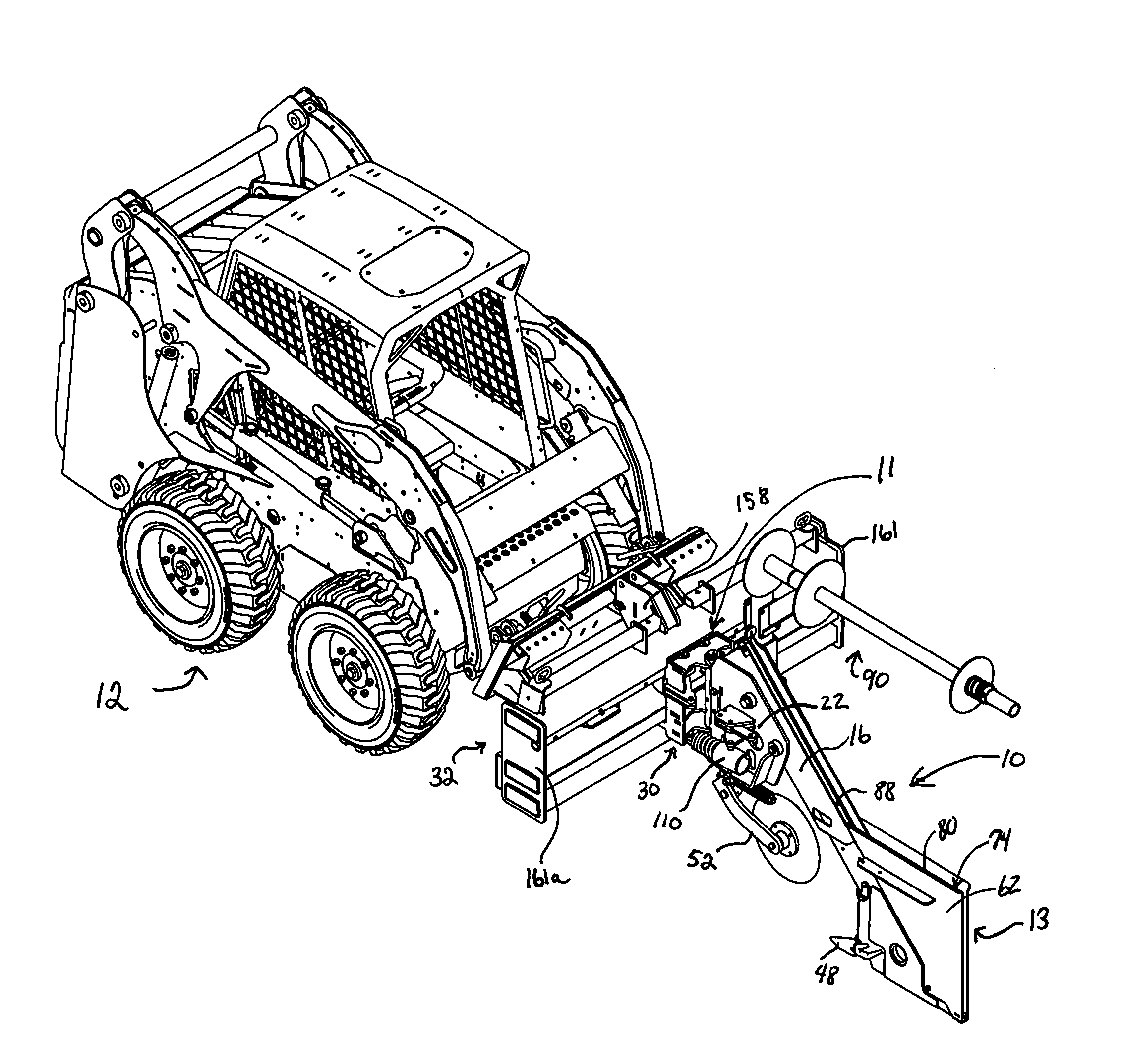
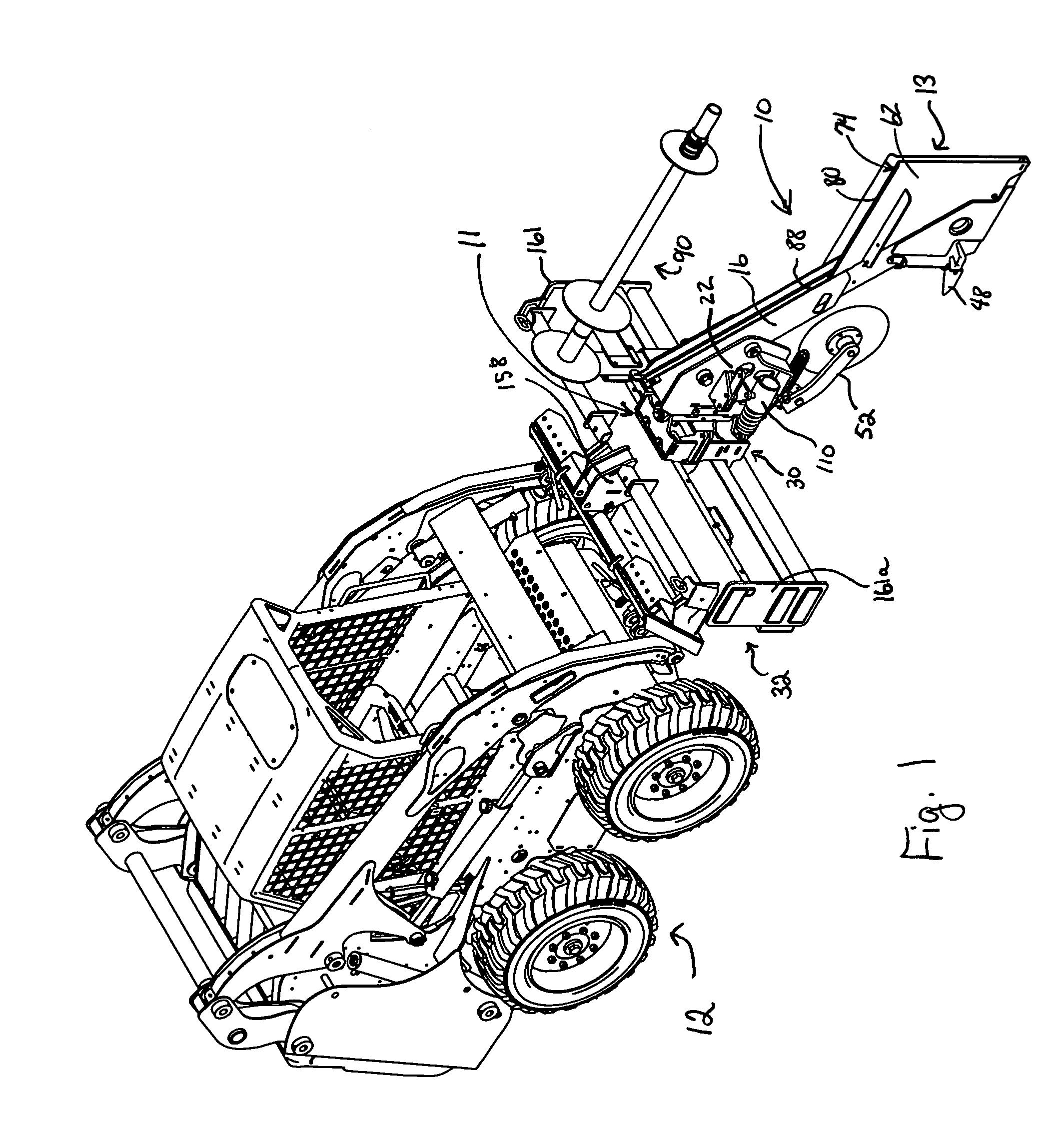
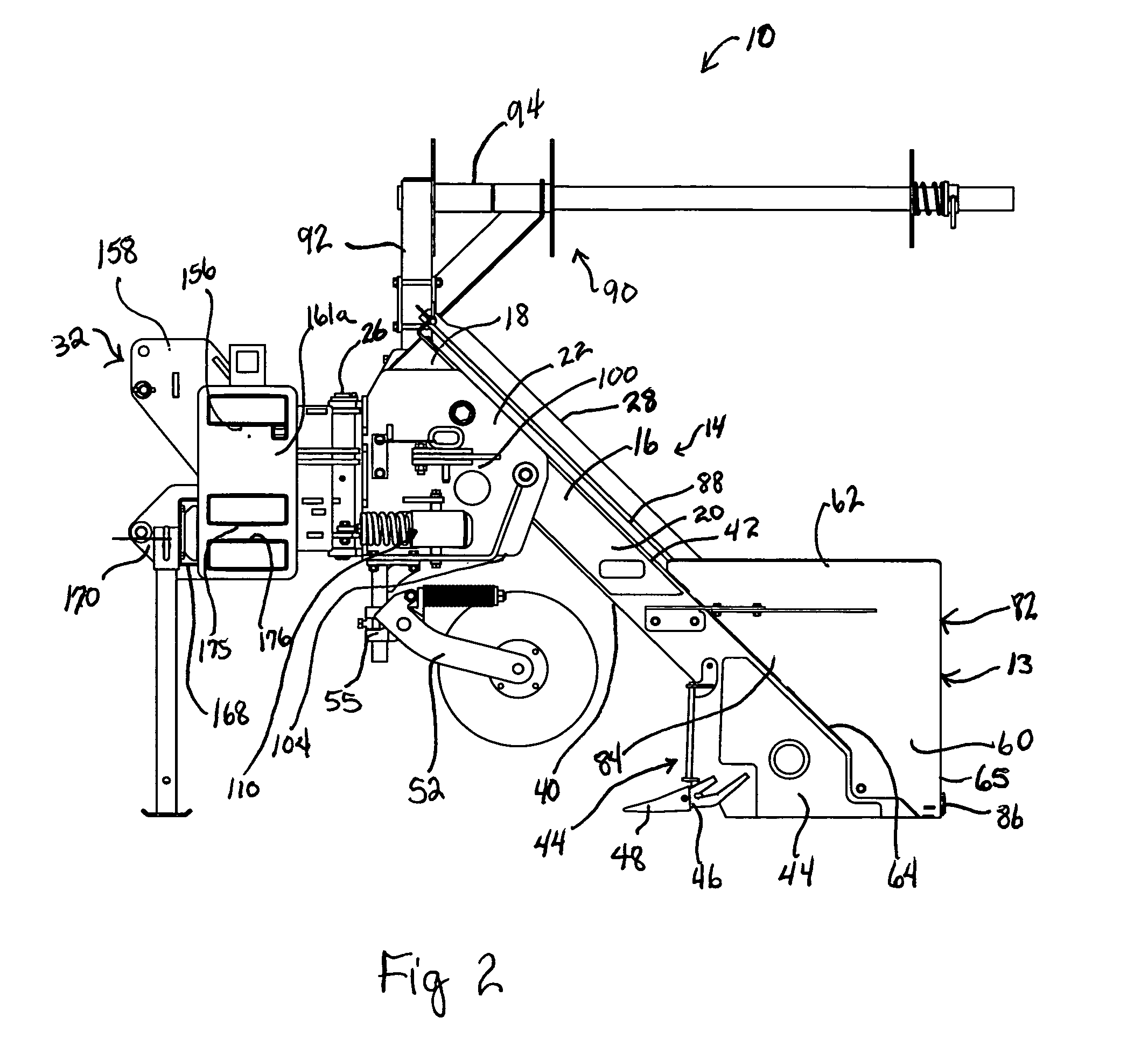
[0035]Referring now to FIG. 1, a perspective of the installer 10 of the present invention having a leading edge 11 and a trailing edge 13 is shown hitched to a towing vehicle 12. Shown in more detail in FIGS. 2-5, the installer 10 of the present invention relies on a frame assembly 14 having a main angular frame support 16 comprising an upper portion 18 and a lower portion 20 said support 16 is affixed to at least one vertically oriented frame member 22 comprising a hitching side 24 equipped with means for associating a hitch assembly 26 and a mounting side 28. The vertically oriented frame member 22 is pivotally associated by said means for associating a hitch assembly 26 with a sliding offset bracket assembly 30 which is, in turn, slidably mounted on a sliding offset hitch 32. Due to the use of rollers 34 and 35 (See FIG. 7) in the sliding offset bracket assembly 30, no hydraulic power is necessary to adjust the position of the installer 10 on the hitch 32 relative to the vehicle ...


PUM


Abstract

The present invention is a silt fence installer of unique design wherein the frame is angular rather than longitudinal and the fabric chute assembly is oriented parallel with the angular frame. This arrangement results in an installer with a generally perpendicular trailing edge, a fabric chute assembly with a closed leading edge and no need for hinged relationship between the sidewalls, and simple fabric threading with a single directional turn of the fabric. Further, the angular frame results in a shorter installer able to be more responsive to turns. In addition, the invention includes a sliding offset hitch wherein a silt fence installer may be adjusted laterally by hand due to strategic placement of rollers.

Description

BACKGROUND OF THE INVENTION[0001]1. Field of the Invention[0002]Many construction projects result in sloped areas without ground covering such as plants. Agricultural fields also may include sloping areas. These sloped generally bare areas will erode drastically with time and weather unless they are equipped with conservation tools. Various implements have been devised by which a fabric-like fence can be partially inserted in a soil furrow and secures by posts and the like. The fence acts to reduce the erosion of the soil from above the fence and stop it there. Several fences may be required in a single sloped area.[0003]2. Background of the Invention[0004]U.S. Pat. No. 3,182,459 to Grether provides an installer mounted on the side of a tractor and which automatically adds the posts. This installer includes a fabric chute employing at least one rod as a pivotal directions changer for the fabric.[0005]U.S. Pat. No. 5,915,878 to Carpenter provides an installer wherein the fabric is po...

Claims


Application Information

Patent Timeline
IPC IPC(8): E02D17/20E02D17/13
CPCE02D17/20
Inventor BURCHLAND, AARON
Owner BURCHLAND AARON
Why Eureka
Try Eureka