Method of depositing a thermal barrier by plasma torch

a technology of plasma torch and thermal barrier, which is applied in the field of plasma torch depositing method, can solve the problems of non-vaporized powder particles being separated from the vapor of material, and achieve the effects of less denseness, improved heat dissipation effect and reduced pressure inside the enclosur

Active Publication Date: 2010-07-27
SN DETUDE & DE CONSTR DE MOTEURS DAVIATION S N E C M A
View PDF4 Cites 0 Cited by
  • Summary
  • Abstract
  • Description
  • Claims
  • Application Information

AI Technical Summary

Benefits of technology

[0011]The invention provides a method making it possible firstly to obtain a deposit that combines the technical advantages of a lamellar deposit and of a columnar deposit, i.e. low thermal conductivity, good lifetime, good resistance to erosion, and high yield and deposition rates, and secondly presenting a cost of implementation that is lower than that of the vacuum phase deposition method.
[0033]By means of this disposition, the density of the plasma at the outlet from the nozzles is smaller, and thus the length of time spent by the particles within the plasma is longer. The powder particles are thus better vaporized.

Problems solved by technology

This results in non-vaporized powder particles being separated from the vapor of the material.

Method used


Image

  • Method of depositing a thermal barrier by plasma torch
  • Method of depositing a thermal barrier by plasma torch

Examples


Embodiment Construction

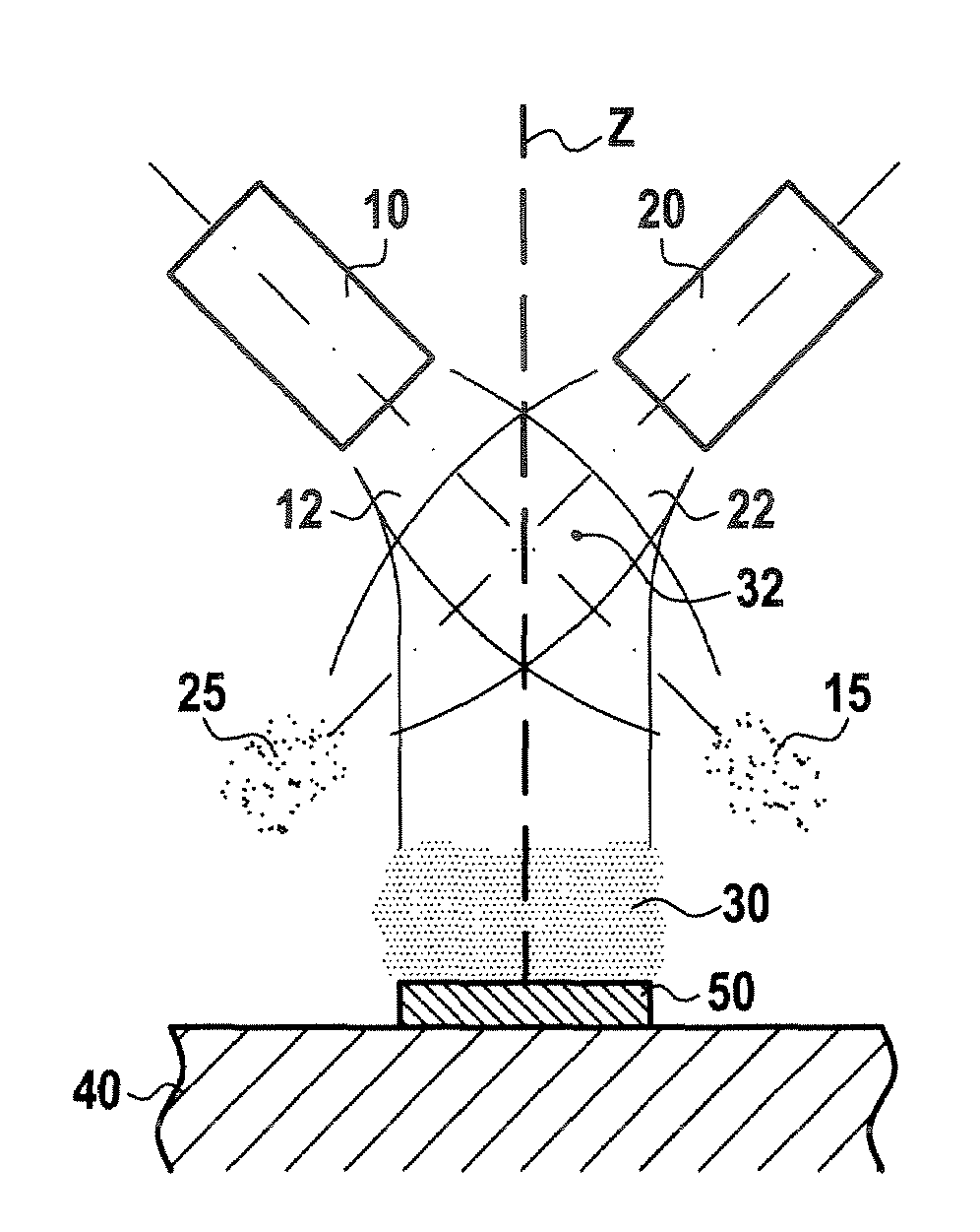
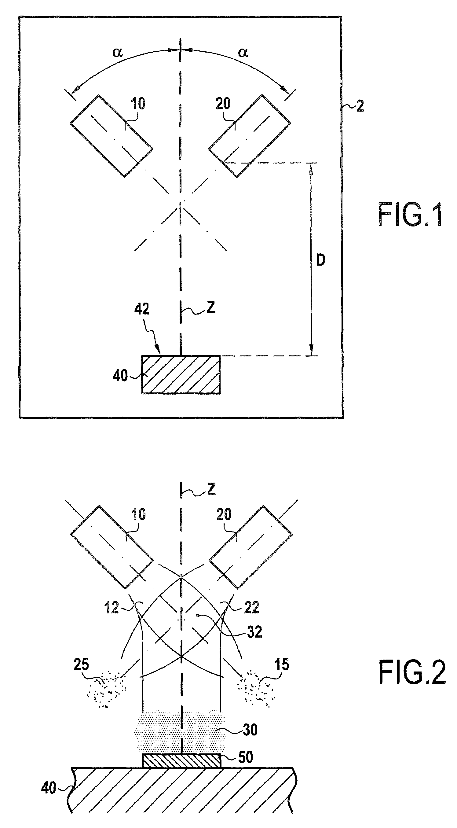
[0038]As shown in FIG. 1, an enclosure 2 has a first plasma torch 10, a second plasma torch 20, and a substrate 40. Each of the first and second plasma torches presents an angle α relative to an axis z directed towards the surface of the substrate that is to receive the deposit (in the example shown, the axis z is perpendicular to the surface of the substrate 40). For reasons of symmetry, the angle α is identical for the first and second plasma torches 10, 20. Nevertheless, the angle α could be different for each of the torches. Ideally, the angle α lies in the range 20° to 60°. The end of each torch from which the plasma jet exits is situated at a distance D from the surface 42 of the substrate 40 that is to receive the deposit, the distance D being measured parallel to the axis z. For reasons of symmetry, the distance D is identical for the first and second plasma torches 10 and 20. Nevertheless, this distance could be different for each of the torches. Ideally, the distance D bet...


PUM

PropertyMeasurementUnit
angleaaaaaaaaaa
distanceaaaaaaaaaa
sizeaaaaaaaaaa

Abstract

The invention relates to the field of methods of depositing a material on a substrate. It relates to a method of depositing, onto a substrate, a material that acts as a thermal barrier and that prior to deposition is in powder form. The powder is introduced into the plasma jet of a first plasma torch and into the plasma jet of at least one second plasma torch, the first plasma torch and at least the second plasma torch being disposed in an enclosure and oriented in such a manner that their plasma jets cross, so as to create a resultant plasma jet in which the powder is vaporized, the substrate being placed on the axis of the resultant plasma jet.

Description

[0001]The present invention relates to a method of depositing, onto a substrate, a material that acts as a thermal barrier, the material being in powder form prior to deposition.BACKGROUND OF THE INVENTION[0002]By way of example, the substrate may be a superalloy, in particular a superalloy for constituting turbomachine parts.[0003]The two technologies that are used industrially for depositing, onto a substrate, a material that acts as a thermal barrier, typically a ceramic, are plasma spraying, and vapor phase deposition.[0004]Plasma spraying consists in injecting the material for deposition in powder form into the plasma jet of a plasma torch. The plasma jet is generated by creating an electric arc between the anode and the cathode of a plasma torch, thereby ionizing the gaseous mixture blown through said arc by the plasma torch. The size of the powder particles injected into the jet lies typically in the range 1 micrometer (μm) to 50 μm. The plasma jet, which reaches a temperatur...

Claims


Application Information

Patent Timeline
Patent Type & Authority Patents(United States)
IPC IPC(8): C23C16/00H05H1/24H05H1/26
CPCH05H1/44H05H1/42Y10T428/31504
Inventor BRAILLARD, FREDERICMENUEY, JUSTINENOGUES, ELISETRICOIRE, AURELIENVARDELLE, MICHEL
Owner SN DETUDE & DE CONSTR DE MOTEURS DAVIATION S N E C M A
Why Eureka
Try Eureka