
Charged particle beam application apparatus

a technology of chargeable particles and application apparatus, which is applied in the direction of muffler furnaces, furnaces, instruments, etc., can solve the problems of specimens catching foreign objects, high manufacturing cost, and substantial increase in prime cost to prepare holder, so as to reduce or eliminate stage setting time, enhance throughput, and secure image precision

Inactive Publication Date: 2010-07-27
HITACHI HIGH-TECH CORP
View PDF24 Cites 10 Cited by
  • Summary
  • Abstract
  • Description
  • Claims
  • Application Information

AI Technical Summary

Benefits of technology

This solution enhances throughput by reducing stage setting time and ensuring image precision, allowing for improved image quality across different specimen sizes without the need for multiple electrostatic chucks, thus reducing overall costs.

Problems solved by technology

An electrostatic chuck is very effective as the specimen holding means in a vacuum, but is generally made of ceramics and its manufacture cost is high.
Accordingly, it leads to substantial increase in prime cost to prepare a holder attachable and detachable to and from a stage as the specimen holding means for each specimen size.
Further, when the electrostatic chuck is fixed to the stage, if the specimen size is switched to a small specimen size, the surface to which the specimen is not sucked appears, which is highly likely to suck foreign matters, and when the specimen size is switched to a large specimen size, there is the fear that the specimen catches the foreign matters, and the specimen surface distorts.
As a result, substantial increase in prime cost is inevitable.

Method used


Image

  • Charged particle beam application apparatus
  • Charged particle beam application apparatus
  • Charged particle beam application apparatus

Examples


Embodiment Construction

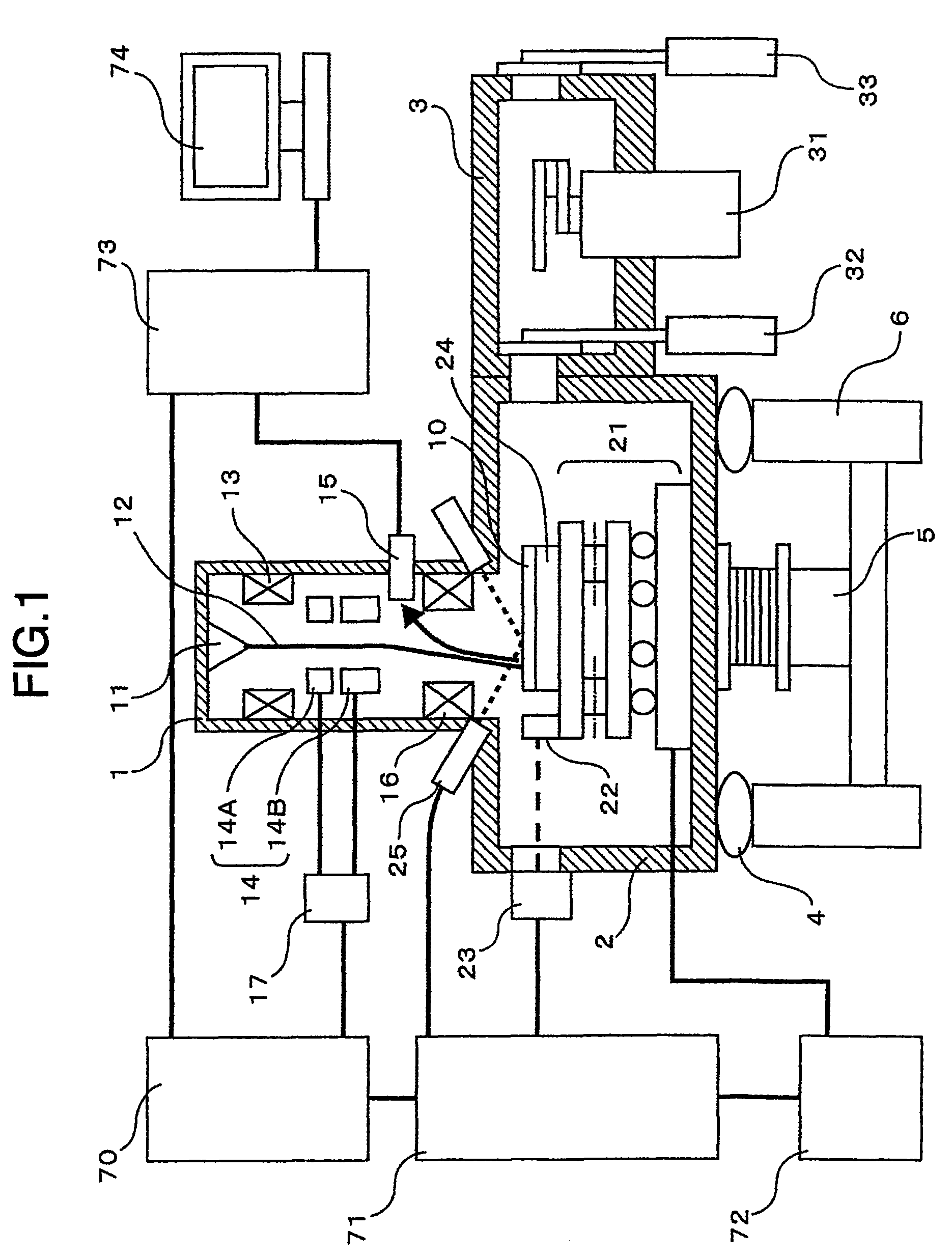
[0029]The present invention will be described with reference to FIGS. 1 to 3, by taking a scanning electron microscope as an example as a charged particle beam application apparatus to which the present invention is applied.

[0030]First, the apparatus constitution shown in FIG. 1 will be described.

[0031]A mount 4 which damps a floor vibration is mounted on a pedestal 6 installed on a floor, and the mount 4 further supports a specimen chamber 2. The specimen chamber 2 is mounted with a column 1 which generates and controls electronic beam, and a load lock 3 containing a transport robot 31 which transports a specimen. The specimen chamber is always evacuated by a vacuum pump 5, and the inside of the column 1 is also kept at a high vacuum degree by a vacuum pump not illustrated. Meanwhile, the load lock 3 is mounted with an atmosphere side gate valve 33 which isolates the load lock 3 from atmosphere, and a vacuum side gate valve 32 which isolates the load lock 3 from the specimen chambe...


PUM


Abstract

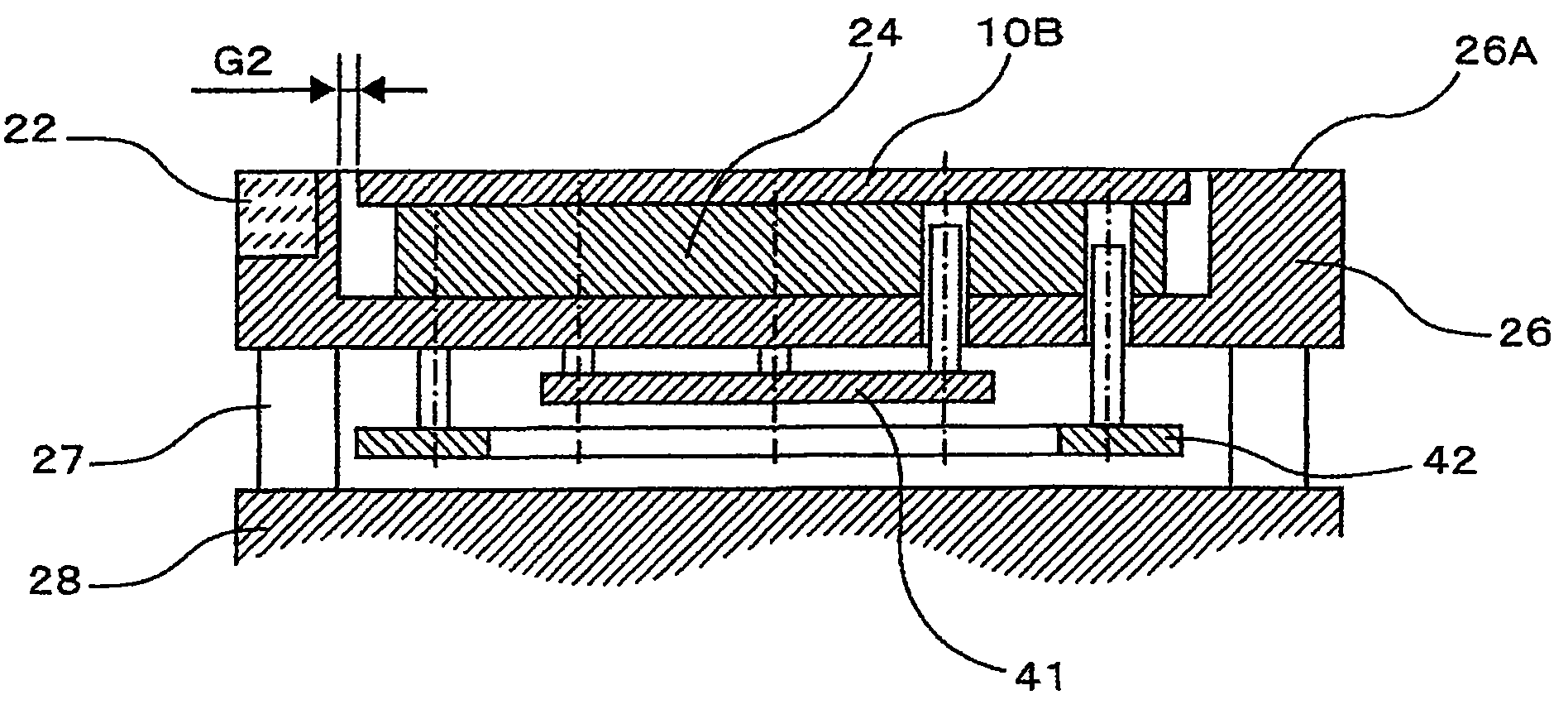
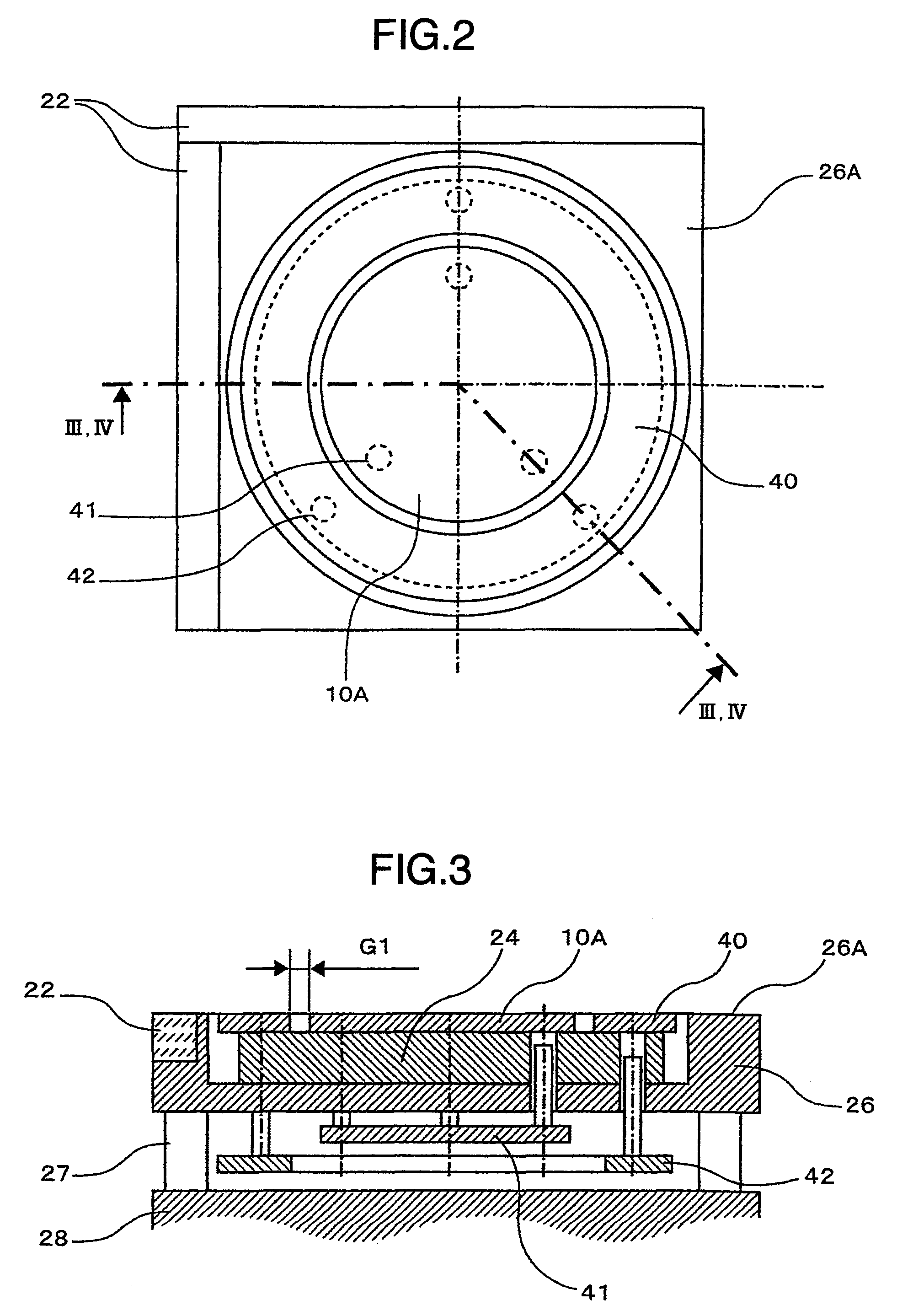
An apparatus capable of improving image quality by making it possible to suck specimens of different sizes electrostatically, and uniformalizing an electric field of a specimen edge portion, while suppressing increase in prime cost is provided. Specimen holding means is an electrostatic chuck, a master flat plane part surrounding a specimen of the largest size of specimen sizes, and an opening surrounding a specimen size except for the largest specimen size are included at an outer peripheral portion of the electrostatic chuck, a dummy specimen attachable to and detachable from the electrostatic chuck is included, and at a time of switching the specimen size, a dummy specimen is selected (or may be prevented from being used).

Description

BACKGROUND OF THE INVENTION[0001]The present invention relates to a charged particle beam application apparatus such as an electron microscope, an ion-beam machining / observation apparatus or the like.[0002]In recent years, the integration densities of semiconductor products have been more and more enhanced, and higher definition of the circuit patterns is demanded. In the specimens on which circuit patterns are formed, typified by semiconductor wafers, various kinds of inspection means are used for the purpose of quality control and enhancement of yield. There are cited, for example, a scanning electron microscope (hereinafter, called a length measuring SEM) which irradiates charged particle beam to measure the dimensional accuracy of a circuit pattern, a scanning electron microscope (hereinafter, called a review SEM) which also irradiates charged particle beam to evaluate a defect of a circuit pattern or attached extraneous matters, and the like.[0003]In the observation of a specim...

Claims


Application Information

Patent Timeline
Patent Type & Authority Patents(United States)
IPC IPC(8): G01F23/00G21K5/10G21K5/08
CPCH01J37/20H01L21/6831H01J2237/2008H01J2237/28H01J2237/2811H01J2237/3174H01J2237/31749
Inventor MIZUOCHI, MASAKITOMIDA, SHOJI
Owner HITACHI HIGH-TECH CORP
Learn More