Road gradient estimating system

a technology of estimating system and road gradient, which is applied in the direction of calibration apparatus, instruments, transportation and packaging, etc., can solve the problems of insufficient accuracy of road gradient calculated in the above manner, and achieve the effect of accurate estimation

Active Publication Date: 2010-07-27
DENSO CORP +1
View PDF14 Cites 5 Cited by
  • Summary
  • Abstract
  • Description
  • Claims
  • Application Information

AI Technical Summary

Benefits of technology

[0007]The present invention is, therefore, made in view of the foregoing problem, and has an object to provide a road gradient estimating system, according to which the road gradient can be more accurately estimated.
[0010]As above, in the case that rate-of-change for the physical amount “Grad0” for the estimated gradient value, which is calculated by subtracting the acceleration “A′” of the vehicle with respect to the road from the vehicle acceleration “A” in the vehicle longitudinal direction, is not regarded as indicating an exact figure due to influences of parameters for disturbance, a limit is set to the physical amount, wherein the limit is set to the rate-of-change for the road gradient depending on the vehicle speed. As a result, it is possible to obtain the physical amount exactly corresponding to the estimated gradient value, namely, to more exactly estimate the road gradient when compared with the conventional method.

Problems solved by technology

However, the above detected acceleration may include various kinds of disturbance parameters, such as variation of acceleration having noise generated when the vehicle climbs over a foreign substance existing on the road, variation of acceleration caused by road undulation, and soon.
Accordingly, the road gradient calculated in the above manner is not always sufficiently accurate.

Method used


Image

  • Road gradient estimating system
  • Road gradient estimating system
  • Road gradient estimating system

Examples


first embodiment

[0043]A first embodiment of the present invention will be hereinafter explained with reference to the drawings. According to the embodiment, a road gradient estimating system of the present invention is applied to a vehicle driving / braking force control system.

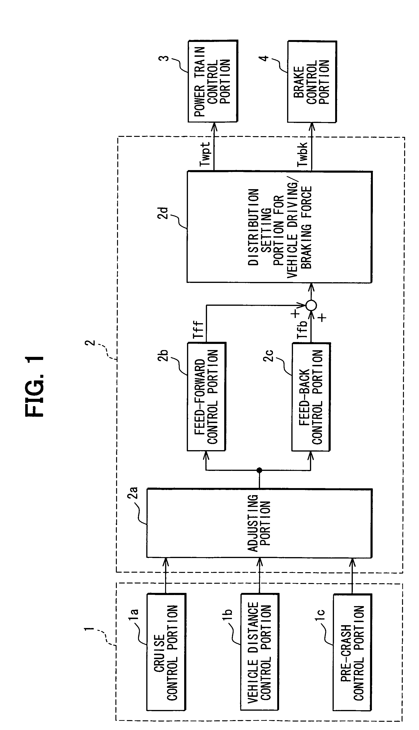
[0044]FIG. 1 is a block diagram schematically showing the vehicle driving / braking force control system. As shown in FIG. 1, the vehicle driving / braking force control system has an acceleration demanding portion 1, a control portion 2 for acceleration in a vehicle longitudinal direction, a power train control portion 3, and a brake control portion 4.

[0045]The acceleration demanding portion 1, which outputs an acceleration demanding signal depending on a vehicle condition, has a cruise control portion 1a, a vehicle distance control portion 1b, and a pre-crash control portion 1c. More exactly, the cruise control portion 1a outputs a demanding signal for acceleration, which is necessary to control a vehicle speed at a constant spe...

second embodiment

[0084]A second embodiment of the present invention will be explained. According to the second embodiment, a map for setting the limiting value with regard to the rate-of-change of the road gradient is changed, which differs from the first embodiment. The remaining portions are the same to the first embodiment. Therefore, a different portion will be explained.

[0085]FIG. 8 is an enlarged map showing a relation between the vehicle speed and the acceleration corresponding value for the limiting value with regard to the rate-of-change for the road gradient, which is memorized in the rate-of-change calculating portion 10. As shown in FIG. 8, a map for a range of vehicle low speed is added to the map shown in FIG. 4.

[0086]When the vehicle starts to move on an uphill slope (or a downhill slope) having a road gradient “θ”, angle of vehicle inclination will be changed during a period from a starting point of a front wheel (the front wheel starts to go up or go down the slope) to an ending poi...

third embodiment

[0093]A third embodiment of the present invention will be explained. According to the third embodiment, manners for setting the limiting value for the rate-of-change of the road gradient and limiting value for the road gradient are changed from the first embodiment. The remaining portions are the same to the first embodiment. Therefore, a different portion will be explained.

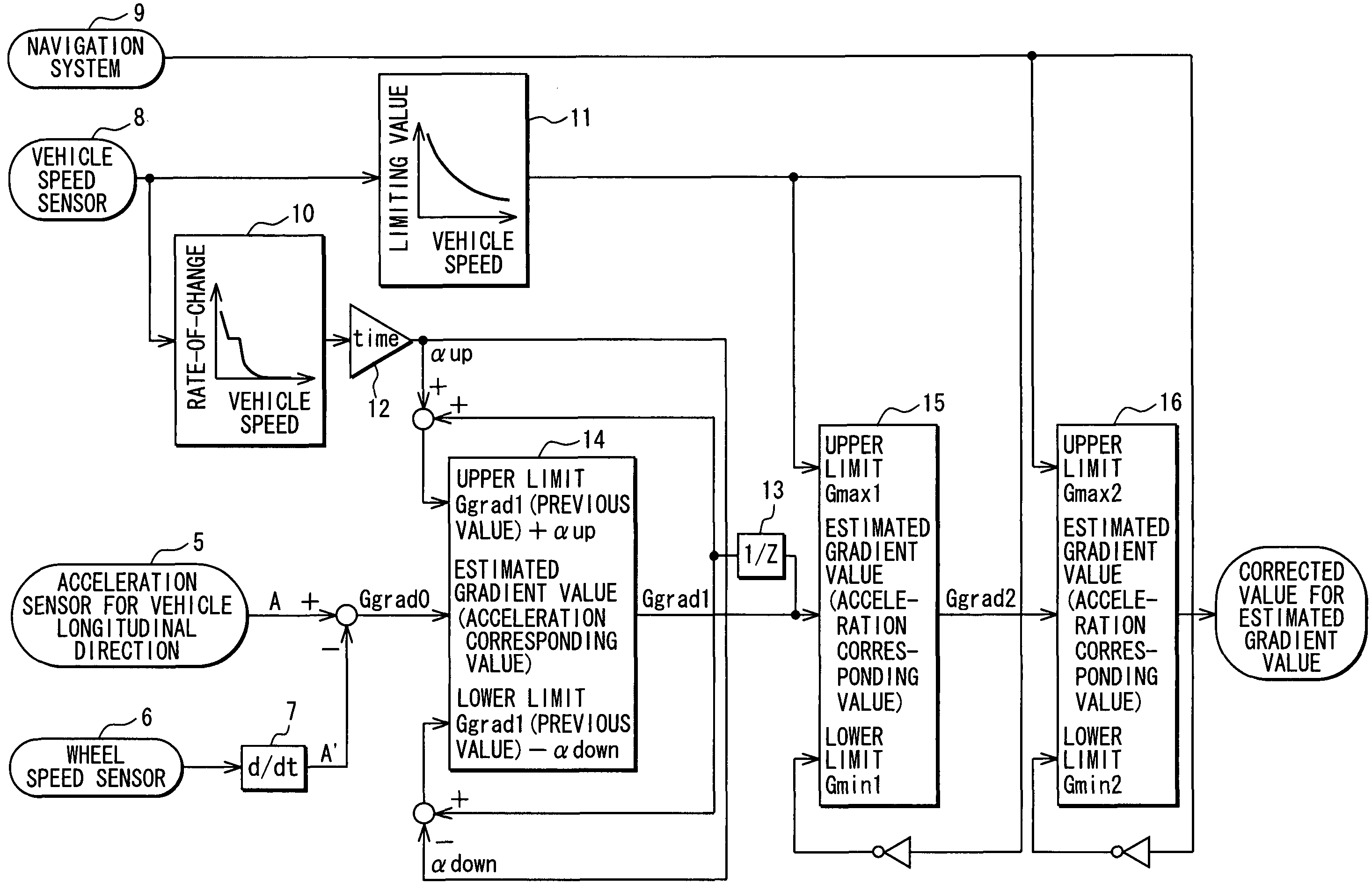
[0094]FIG. 10 is a block diagram schematically showing a road gradient estimating system according to the third embodiment. The road gradient estimating system of this embodiment calculates the acceleration corresponding value “Ggrad0” for the estimated gradient value in the conventional manner. Then, the road gradient estimating system compares the acceleration corresponding value “Ggrad0” with acceleration corresponding values for an upper limit and / or a lower limit of the estimated gradient value, which is decided by a limiting value for rate-of-change of the road gradient or a limiting value for the road grad...


PUM


Abstract

An estimated gradient value of a road is calculated based on a vehicle acceleration “A” and a time varying portion “A′” of a wheel speed. In a case that an acceleration corresponding value “Ggrad0” for the estimated gradient value is not regarded as indicating an exact figure, due to influences of disturbances, the acceleration corresponding value “Ggrad0” is corrected by a limiting value for rate-of-change with regard to the road gradient depending on respective vehicle speed, and by a limiting value for the road gradient. As a result, the acceleration corresponding value “Ggrad” for the estimated gradient value can be more exactly obtained.

Description

CROSS REFERENCE TO RELATED APPLICATION[0001]This application is based on Japanese Patent Application No. 2007-186913 filed on Jul. 18, 2007, the disclosure of which is incorporated herein by reference.FIELD OF THE INVENTION[0002]The present invention relates to a road gradient estimating system for estimating road gradient (an angle of gradient) of a vehicle traveling road in a vehicle traveling direction.BACKGROUND OF THE INVENTION[0003]A method for estimating the road gradient is conventionally proposed, for example, as disclosed in Japanese Patent Publication No. H02-161308, according to which the road gradient is estimated based on vehicle acceleration in a vehicle longitudinal direction detected by an acceleration sensor provided on a vehicle as well as acceleration of the vehicle with respect to the road. The acceleration of the vehicle with respect to the road is, for example, acceleration for a component of gravity (which corresponds to the road gradient), which is calculate...

Claims


Application Information

Patent Timeline
Patent Type & Authority Patents(United States)
IPC IPC(8): G01C9/00
CPCB60W30/143G01C9/00B60W40/072B60W40/076B60W2550/142B60W2552/15
Inventor OSAKI, SHINTAROKODAMA, HIROYUKITAKEDA, MASAYOSHIKADOWAKI, KAZUNORIKUMABE, HAJIMENAKAI, YASUHIRONIWA, SATOSHIFUKUDA, SYOTAROU
Owner DENSO CORP
Why Eureka
Try Eureka