Apparatus and method for pressure relief in an exhaust brake

a technology of exhaust brake and apparatus, which is applied in the direction of mechanical apparatus, lift valves, valve details, etc., can solve the problem of too small restriction in effect, and achieve the effect of preventing excessive pressure buildup

Active Publication Date: 2010-08-03
JENARA ENTERPRISES
View PDF25 Cites 12 Cited by
  • Summary
  • Abstract
  • Description
  • Claims
  • Application Information

AI Technical Summary

Benefits of technology

[0005]There is provided, according to one aspect of the invention, an exhaust brake comprising a body having a passageway for exhaust gases therein. A valve member is movably located within the passageway for selective movement between an open position, where the valve member opens the passageway and exhaust gases are free to move through the passageway, and a closed position where the valve member blocks the passageway and the passage of exhaust gases through the passageway. The valve member has an aperture therethrough to permit a limited flow of exhaust gases through the aperture when the aperture is open. An exhaust valve actuator mechanism is coupled to the valve member for moving the valve member between the open position and the closed position. A closure member is positioned adjacent to the aperture. The closure member has an open position where the closure member is spaced apart from the valve member and permits a flow of exhaust gases through the aperture. The closure member has a closed position where the closure member contacts the valve member about the aperture and prevents a flow of exhaust gases through the aperture. There is a relief actuator mechanism, the relief actuator mechanism including an actuator member which operatively engages the closure member. The relief mechanism brings the closure member into operative engagement with the valve member with sufficient force, when the valve member is closed, to maintain the closure member in the closed position when the exhaust gases are below a predetermined pressure.
[0006]According to another aspect of the invention, there is provided a method for preventing excessive pressure buildup in an exhaust brake for an internal combustion engine, said brake having a passageway for exhaust gases, a valve member movably located within the passageway for selective movement between an open position, where the valve member opens the passageway and exhaust gases are free to move through the passageway, and a closed position where the valve member blocks the passageway and inhibits the passage of exhaust gases through the passageway. The method includes providing an aperture through the valve member to permit a limited flow of exhaust gases through the aperture when the aperture is open. A closure member is positioned adjacent to the aperture so the closure member has an open position where the closure member is spaced apart from the valve member and permits a flow of exhaust gases through the aperture. The closure member has a closed position where the closure member contacts the valve member about the aperture and prevents a flow of exhaust gases through the aperture. A relief actuator mechanism is provided and includes an actuator member which operatively engages the closure member. The closure member is brought into operative engagement with the valve member with sufficient force, when the valve member is closed, to maintain the closure member in the closed position when the exhaust gases are below a predetermined pressure.

Problems solved by technology

The restriction is accordingly too small to be effective with the lower mass flow rates encountered at lower engine speeds.

Method used


Image

  • Apparatus and method for pressure relief in an exhaust brake
  • Apparatus and method for pressure relief in an exhaust brake
  • Apparatus and method for pressure relief in an exhaust brake

Examples


Embodiment Construction

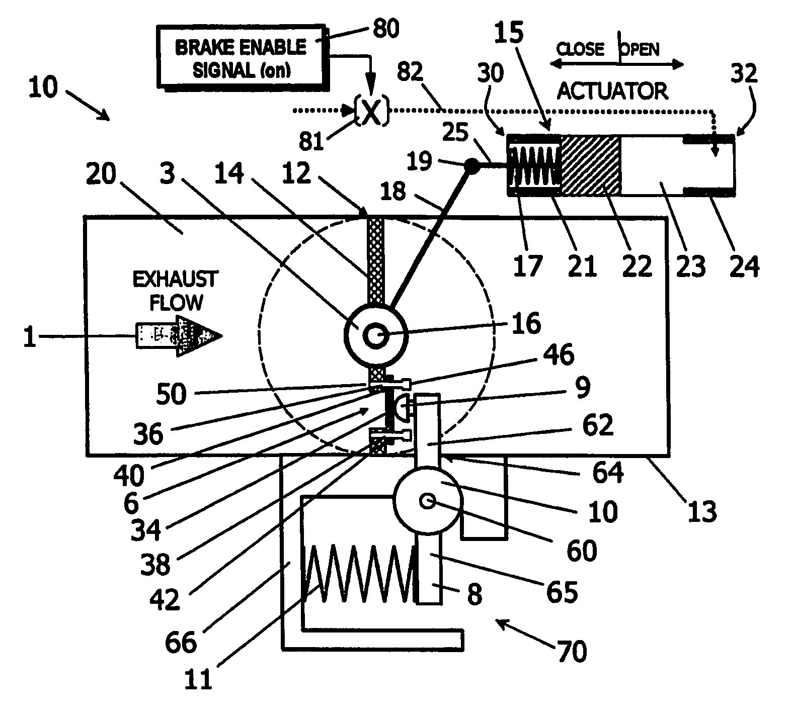
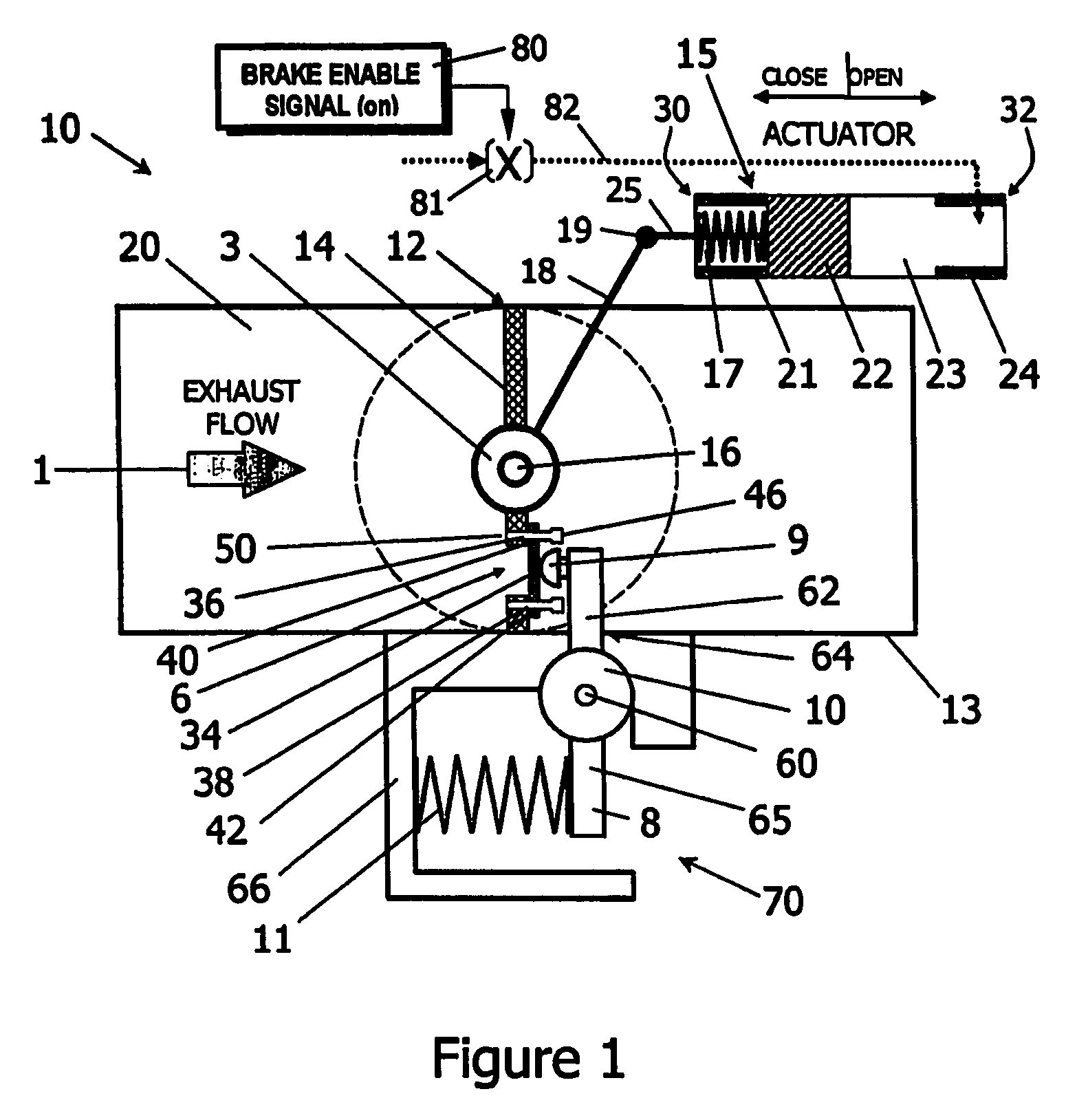
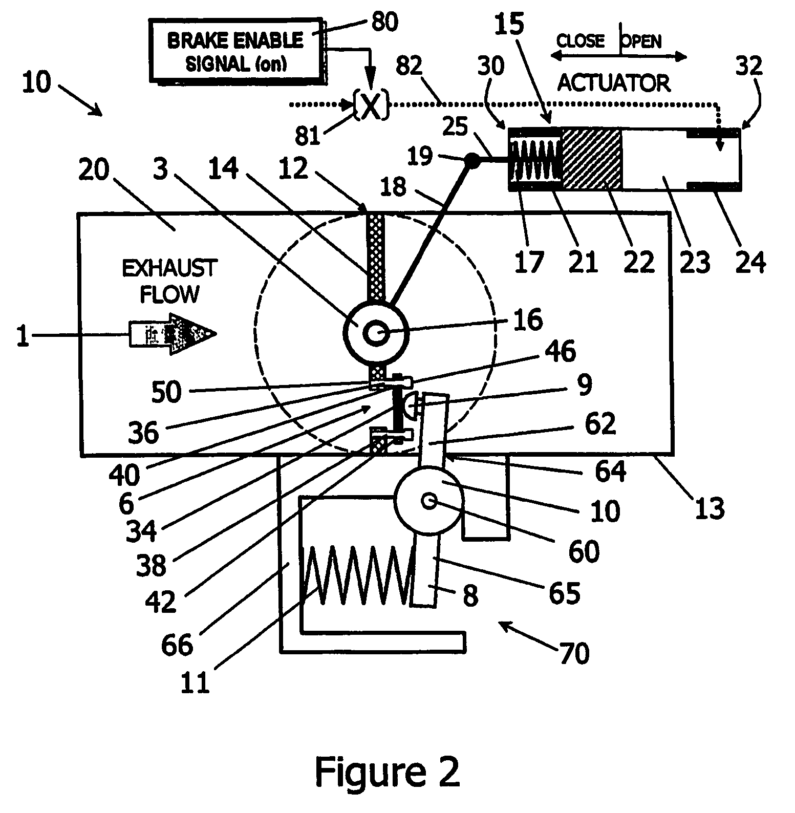
[0019]Referring to FIGS. 1-3, pressure relief exhaust brake 10 in this example includes a butterfly valve 12 including a valve member 14 that is rotatable about a shaft 16. Other types of valves could be used in other embodiments, such as gate valves. The valve member 14 may be replaced by other movable elements that may be placed in the engine exhaust system.

[0020]The valve member 14 is located in body 13. FIG. 7 shows an engine 100 including an exhaust manifold 101, an exhaust conduit 102 and the exhaust brake 10. The exhaust brake is connected to the exhaust manifold by the exhaust conduit. Referring back to FIGS. 1-3, the body has a passageway 20 for exhaust gases discharged by the engine.

[0021]When completely closed, as seen in FIG. 1, the valve member in this example occupies substantially the entire area of the passageway and accordingly blocks a flow of exhaust gases from the engine. The valve member may completely stop a flow of exhaust gases through the passageway 20, apar...


PUM


Abstract

An exhaust brake has a body with a passageway for exhaust gases therein. A valve member is movably located within the passageway for selective movement between an open position where the valve member opens the passageway and exhaust gases are free to move through the passageway and a closed position where the valve member blocks the passageway and the passage of exhaust gases through the passageway. The valve member has an aperture therethrough to permit a limited flow of exhaust gases through the aperture when the aperture is open. An exhaust valve actuator mechanism is coupled to the valve member for moving the valve member between the open position and the closed position. A closure member is positioned adjacent to the aperture. The closure member has an open position where the closure member is spaced apart from the valve member and permits a flow of exhaust gases through the aperture and the closure member having a closed position where the closure member contacts the valve member about the aperture and inhibits a flow of exhaust gases through the aperture, An actuator member operatively engages the closure member. There is a relief actuator mechanism, the relief actuator mechanism including an actuator member that operatively engages the closure member. The relief mechanism brings the closure member into operative engagement with the valve member with sufficient force, when the valve member is closed, to maintain the closure member in the closed position when the exhaust gases are below a predetermined pressure.

Description

BACKGROUND OF THE INVENTION[0001]This invention relates to an exhaust brake with a pressure relief device, an engine equipped with an exhaust brake and the pressure relief device, as well as to a method of preventing a buildup of excessive pressure in an exhaust brake.[0002]Diesel engines in vehicles, particularly larger trucks, are commonly equipped with exhaust brakes for engine retarding. An exhaust brake consists of a restrictor element mounted in the exhaust system. When this restrictor closes, back pressure resists the exit of gases during the exhaust cycle and provides braking power for the vehicle.[0003]With conventional fixed geometry exhaust brakes, the retarding power decreases sharply as engine speed decreases. This occurs because the restriction is typically optimized to generate maximum allowable back pressure at rated engine speed. The restriction is accordingly too small to be effective with the lower mass flow rates encountered at lower engine speeds.[0004]Systems h...

Claims


Application Information

Patent Timeline
Patent Type & Authority Patents(United States)
IPC IPC(8): F02D9/06F02D9/00F02D9/10F02D9/16
CPCF02D9/06F02D9/102F02D9/1025F02D9/1055F02D9/16Y10T137/87378
Inventor LHOTE, ANDRE F.MENEELY, VINCENT A.GAVRIL, GABRIELSPENCE, TAMARAHARTLEY, JOHN P.
Owner JENARA ENTERPRISES
Why Eureka
Try Eureka