
Multiplexed latching valves for microfluidic devices and processors

a technology of microfluidic devices and processors, applied in the field of microfluidic structures, can solve the problems of slowed realization of this goal, significant decreases in overall sequencing time and cost, and valving and pumping technologies, and achieve the effect of reducing the size, power consumption, and cost of microfluidic lab-on-a-chip devices

Active Publication Date: 2010-08-03
RGT UNIV OF CALIFORNIA
View PDF154 Cites 68 Cited by
  • Summary
  • Abstract
  • Description
  • Claims
  • Application Information

AI Technical Summary

Benefits of technology

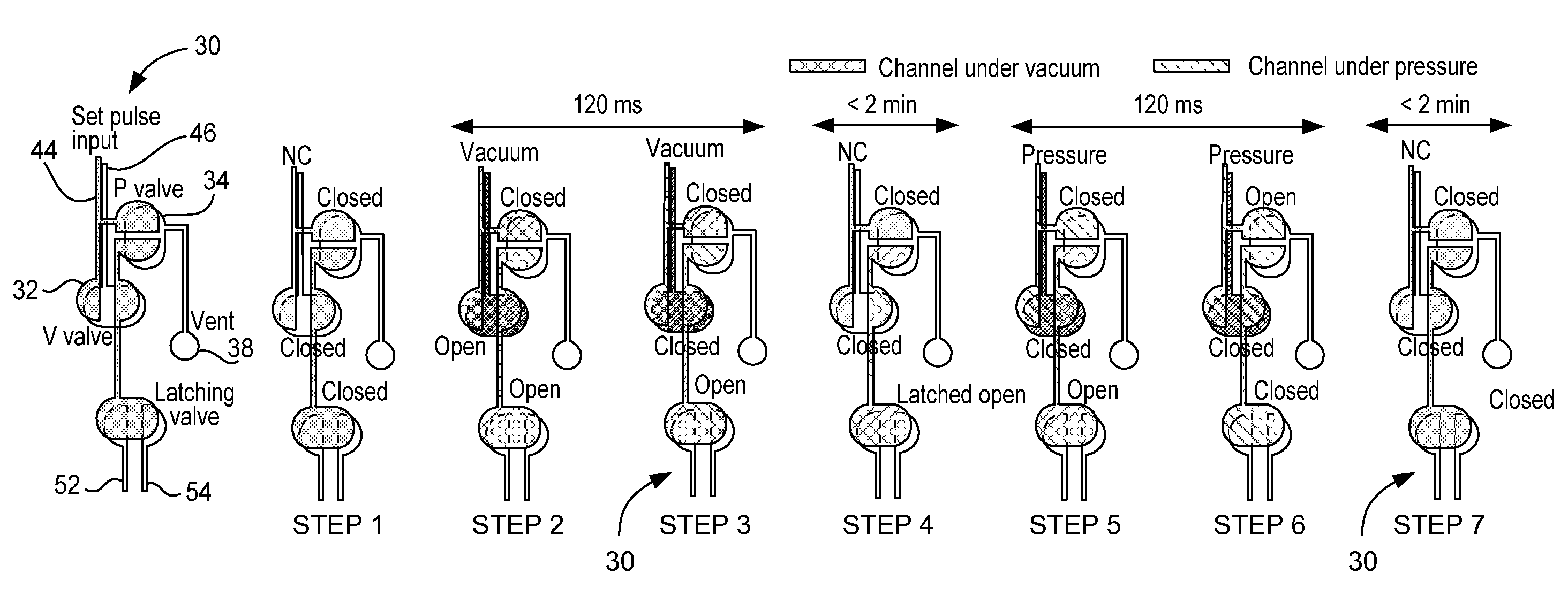
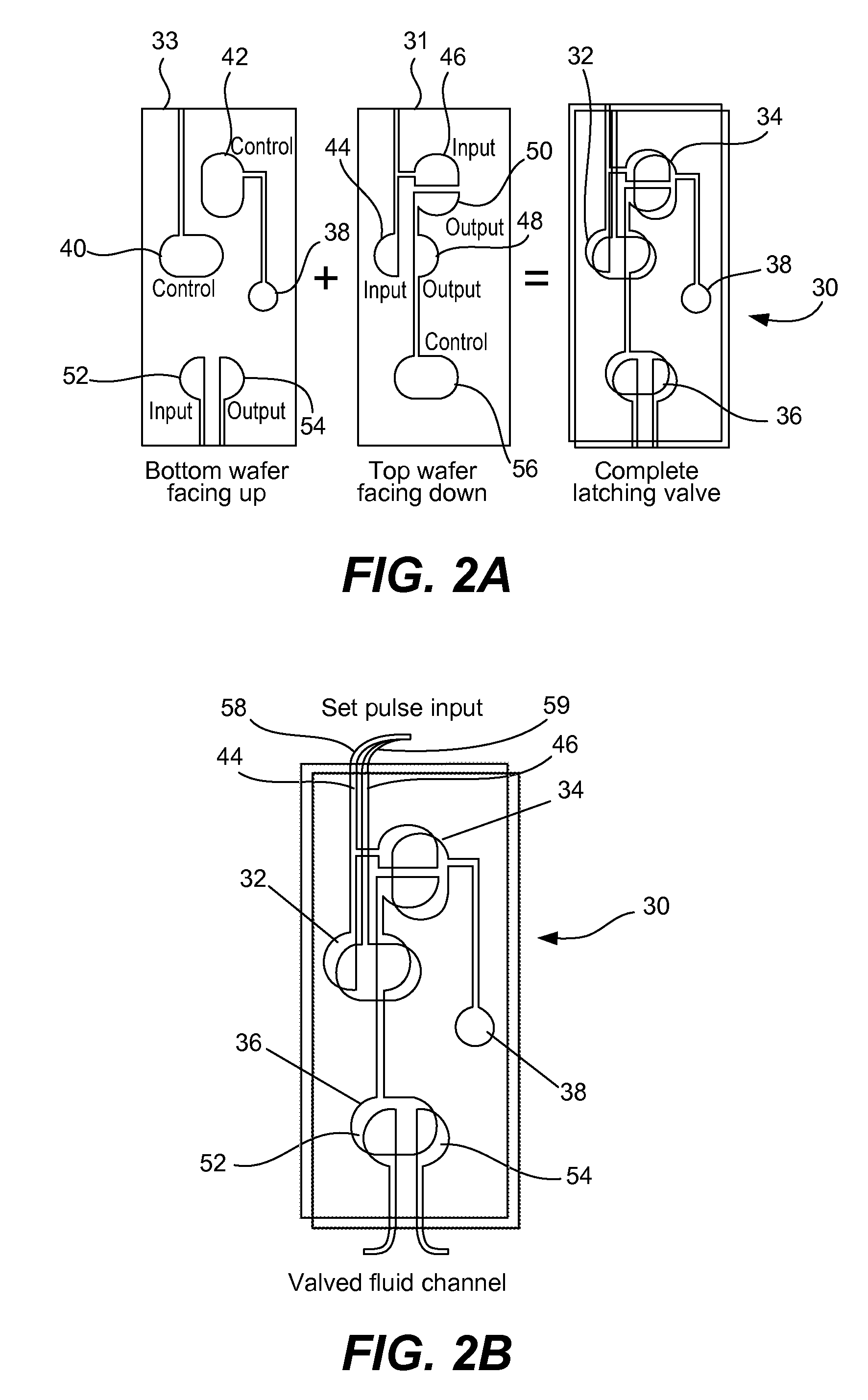
[0012]The invention can include one or more of the following advantages. Large numbers of multiplexed latching valve structures can be independently controlled by a small number of pneumatic lines, thereby reducing the size, power consumption, and cost of microfluidic lab-on-a-chip devices. That is, the latching valve structures can control microfluidic flow with a minimum of chip to world pneumatic interfaces. This includes but goes beyond multiplexers. These structures also enable the development of pneumatic logic processors. Monolithic valves and structures can be configured to function as transistors in pneumatic digital logic circuits. Using the analogy with N-channel MOSFETs, networks of pneumatically actuated microvalves can provide pneumatic digital logic gates (AND, OR, NOT, NAND, and XOR). These logic gates can be combined to form complex logical circuits like ripple carry adders. The invention also enables the development of digital pneumatic computing and logic systems that are immune to electromagnetic interference.

Problems solved by technology

For example, in the field of genomics, the integration of operations like colony picking, sequencing sample amplification, purification, and electrophoretic analysis into a high-throughput parallel platform will result in significant decreases in overall sequencing time and cost.
Realization of this goal has been slowed by the lack of valving and pumping technologies suitable for use in highly-serial, highly-parallel microdevices.
These devices may require hundreds of valves to be actuated in parallel, while simultaneously hundreds of other valves are actuated one-by-one—an extremely demanding set of requirements.
The power consumption, cost, and size of solenoid valves preclude their use in large numbers, and excessive pneumatic connections to the microfluidic device waste useful on-chip space.
These silicon- or polymer-based valves are chemically and physically unsuitable for many lab-on-a-chip assays, are complex to fabricate, and cannot be easily arrayed for parallel or multiplexed actuation.
Previous demultiplexers allow for addressing of individual microreactors in an array but not the more-useful, arbitrary control of independent valves.
Also, the row / column addressing method employed previously imposes significant restrictions on the geometry of the device and limits the number of microreactors addressable by n control lines to only 2(n / 2).

Method used


Image

  • Multiplexed latching valves for microfluidic devices and processors
  • Multiplexed latching valves for microfluidic devices and processors
  • Multiplexed latching valves for microfluidic devices and processors

Examples


Embodiment Construction

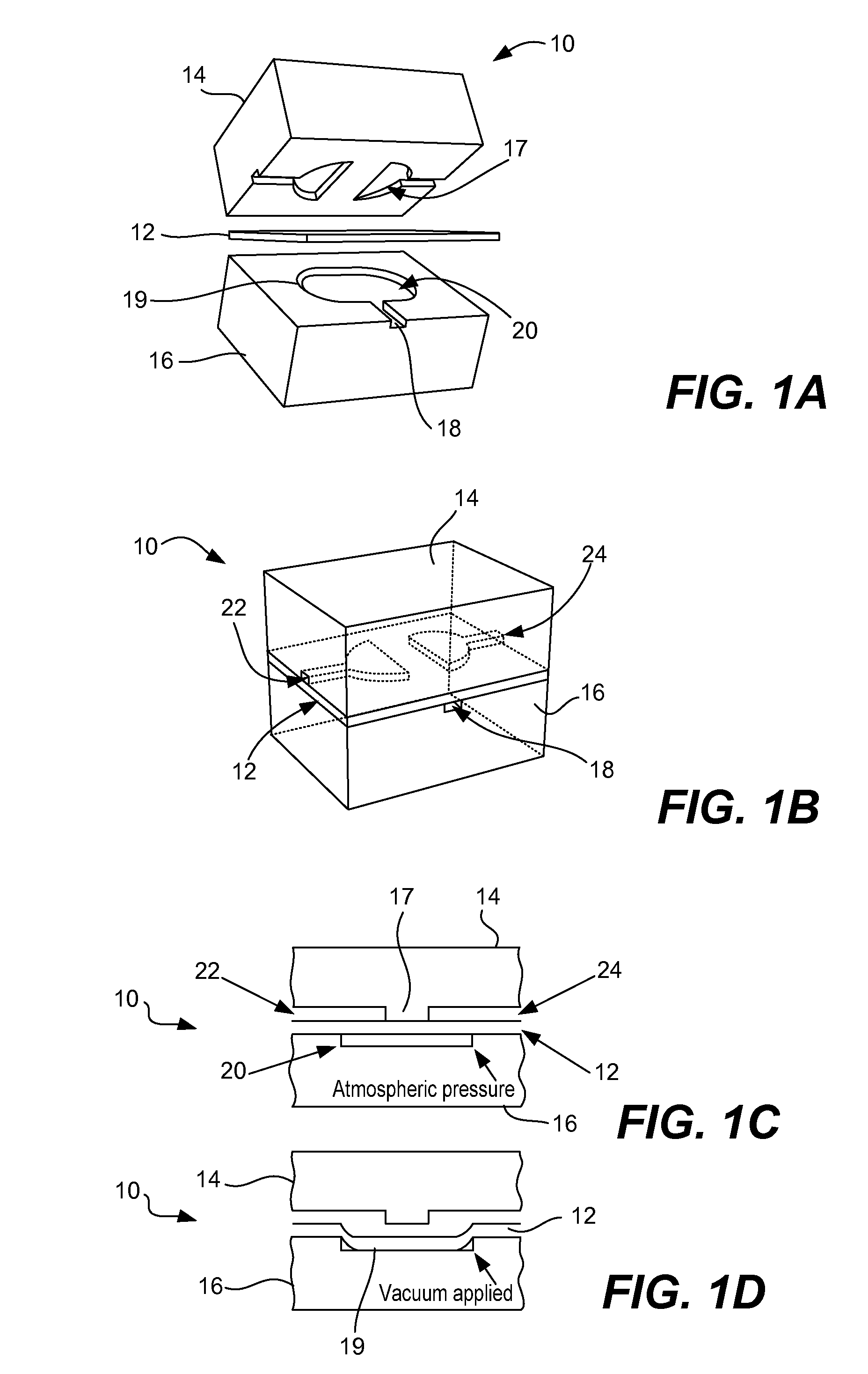
[0041]Reference will now be made in detail to some specific embodiments of the invention including the best modes contemplated by the inventors for carrying out the invention. Examples of these specific embodiments are illustrated in the accompanying drawings. While the invention is described in conjunction with these specific embodiments, it will be understood that it is not intended to limit the invention to the described embodiments. On the contrary, it is intended to cover alternatives, modifications, and equivalents as may be included within the spirit and scope of the invention as defined by the appended claims. For example, the techniques of the present invention will be described in the context of glass microfluidic devices, although other devices such as plastic or polymer devices could also be used.

[0042]It should be noted that the fluid control structures suitable for use in microfluidic devices can be applied to a variety of microfluidic devices. A pathogen detection sys...


PUM


Abstract

Membrane valves and latching valve structures for microfluidic devices are provided. A demultiplexer can be used to address the latching valve structures. The membrane valves and latching valve structures may be used to form pneumatic logic circuits, including processors.

Description

CROSS-REFERENCE TO RELATED APPLICATIONS[0001]This application claims priority under 35 U.S.C. 119(e) from Provisional U.S. Patent Application Ser. No. 60 / 785,005, filed Mar. 22, 2006, entitled “Multiplexed Latching Valves For Complex Microfluidic Devices And Processors”, which is incorporated herein by reference.BACKGROUND OF THE INVENTION[0002]1. Field of the Invention[0003]The present invention relates to microfluidic structures. In one example, the present invention relates to membrane valves and structures that control microfluidic flow and that can be combined to perform complex pneumatic logical operations.[0004]2. Description of Related Art[0005]Modern microfluidic analysis devices having evolved considerably from early single-channel, single-step devices. Highly-parallel, multi-channel devices now increase throughput by performing hundreds of assays simultaneously, and lab-on-a-chip devices now integrate complex multi-step preparation and analysis operations into a single po...

Claims


Application Information

Patent Timeline
Patent Type & Authority Patents(United States)
IPC IPC(8): F16K31/128B01L99/00
CPCB01L3/502738F16K99/0001F16K99/0015F16K99/0059B01L3/5025B01L2200/12B01L2300/0816B01L2300/0887B01L2400/0638F16K99/0034F16K2099/0071F16K2099/0074F16K2099/0084Y10T137/87249Y10T137/2218Y10T137/3115Y10T137/5474G01N35/00
Inventor MATHIES, RICHARD A.GROVER, WILLIAM H.JENSEN, ERIK C.
Owner RGT UNIV OF CALIFORNIA
Learn More