Posterior stabilization system

a stabilization system and posterior vertebrae technology, applied in the field of spinal instrumentation, can solve the problems of limiting the use of capping techniques, pain, neurological dysfunction, and kyphosis (abnormal forward curvature of the spine), and achieve the effect of limiting the axial rotation of adjacent vertebra

Active Publication Date: 2010-08-03
DEPUY SPINE INC (US)
View PDF172 Cites 49 Cited by
  • Summary
  • Abstract
  • Description
  • Claims
  • Application Information

AI Technical Summary

Benefits of technology

[0007]The present invention provides various methods and devices for repairing and / or replacing a facet joint, and optionally for replacing other posterior elements, including, for example, the lamina, the posterior ligaments, and / or other features of a patient's spinal column. In one exemplary embodiment, an implant for stabilizing the spine is provided and it can include a first member that is adapted to couple to a first vertebra and a second member that is adapted to couple to a second vertebra adjacent to the first vertebra. The first and second members can be movable relative to one another such that the implant is adapted to control flexion, extension, and lateral bending of the first and second adjacent vertebrae relative to one another, and it is adapted to substantially prevent axial rotation of the first and second adjacent vertebrae relative to one another.
[0011]In other exemplary embodiments, a method for stabilizing the posterior element in adjacent vertebrae is provided and includes implanting a spinal prosthesis between adjacent vertebrae. The spinal prosthesis can have an artificial disc that is movable relative to the adjacent vertebrae such that the spinal prosthesis has a predetermined envelope of motion. The method further includes coupling a posterior implant to the adjacent vertebrae. In an exemplary embodiment, the posterior implant has an envelope of motion that is within the envelope of motion of the spinal prosthesis such that the posterior implant is adapted to control flexion, extension, and lateral bending of the adjacent vertebrae relative to one another, and to substantially limit axial rotation of the adjacent vertebrae relative to one another. The method can also include, prior to coupling a posterior implant to the adjacent vertebrae, determining a desired envelope of motion of a posterior implant based on an image of the spinal prosthesis disposed between the adjacent vertebrae, and selecting a posterior implant having an envelope of motion that corresponds to the desired envelope of motion. In another exemplary embodiment, coupling a posterior implant to adjacent vertebrae can include coupling a first member to a vertebra, and coupling a second member to an adjacent vertebra. The first and second members can be movably coupled to one another. In yet another exemplary embodiment, implanting a spinal prosthesis between adjacent vertebrae can include positioning first and second endplates with the artificial disc disposed therebetween between the adjacent vertebrae.

Problems solved by technology

Subsequent surgery may also be required after a laminectomy, as a laminectomy predisposes the patient to instability and may lead to post-laminectomy kyphosis (abnormal forward curvature of the spine), pain, and neurological dysfunction.
As a result, additional stress may be applied to the adjoining levels, thereby potentially leading to further damage.
Capping techniques, however, are limited in use as they will not remove the source of the pain in osteoarthritic joints.
Caps are also disadvantageous as they must be available in a variety of sizes and shapes to accommodate the wide variability in the anatomical morphology of the facets.
Caps also have a tendency to loosen over time, potentially resulting in additional damage to the joint and / or the bone support structure containing the cap.
However, aligning two articulating rigid surfaces for facet replacements can be very difficult given the variations in patient anatomy and various motion required (i.e., flexion, extension, lateral bending, and translations).

Method used


Image

  • Posterior stabilization system
  • Posterior stabilization system
  • Posterior stabilization system

Examples


Embodiment Construction

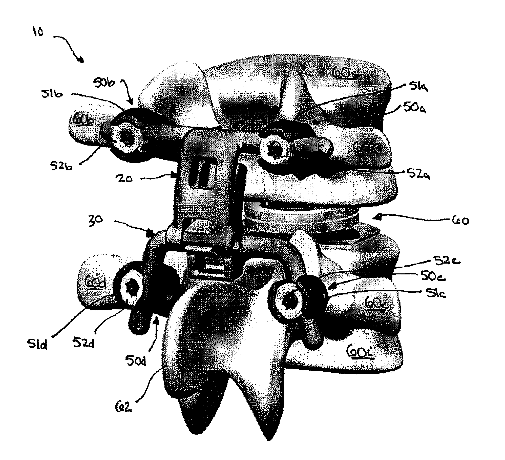
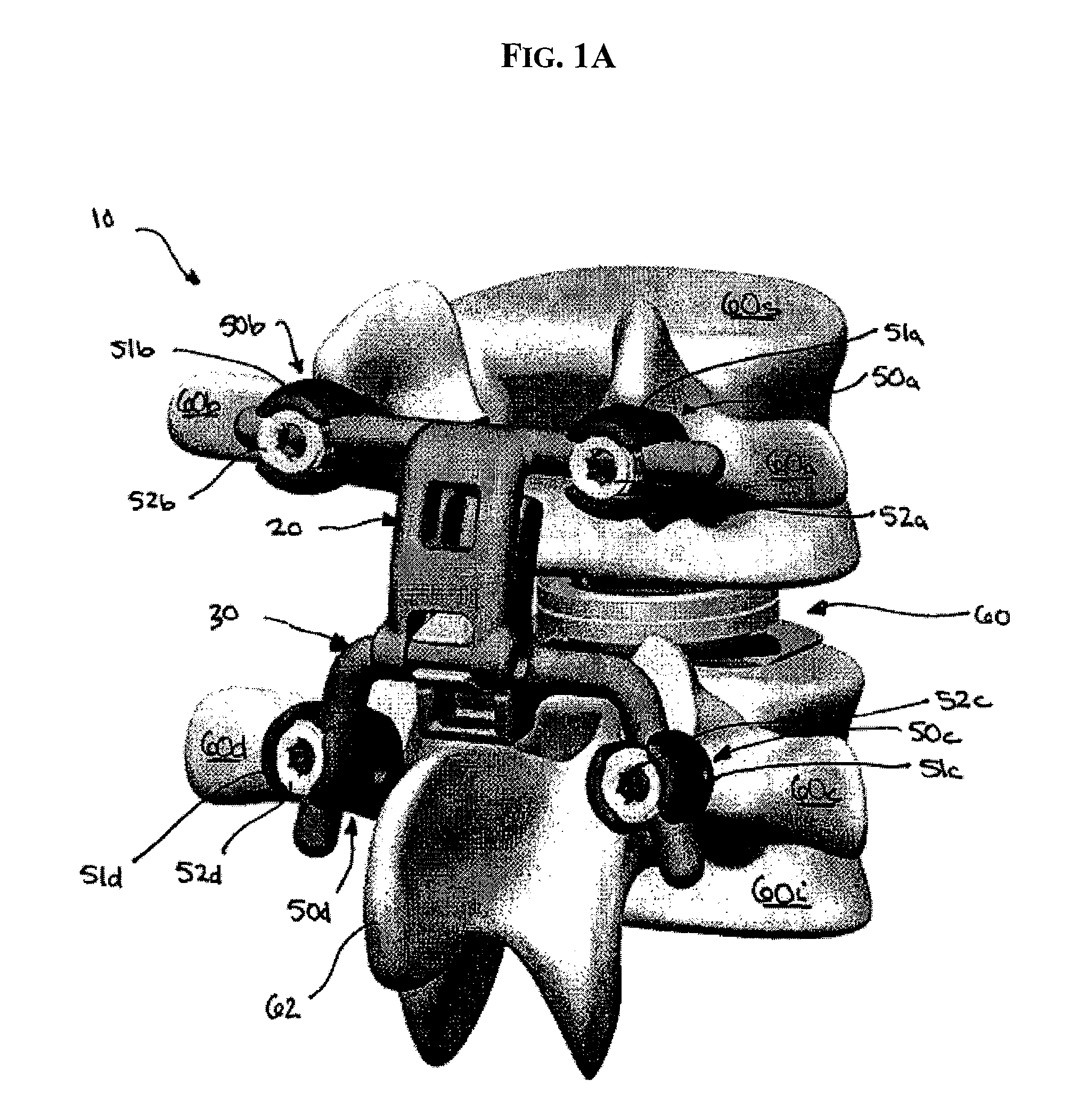
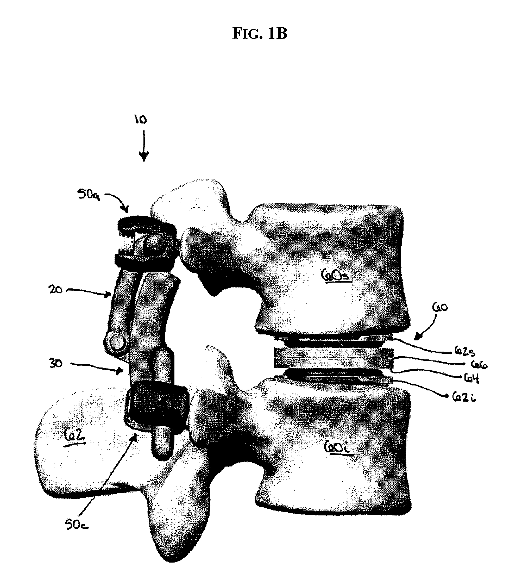
[0021]The present invention provides various methods and devices for replacing damaged, injured, diseased, or otherwise unhealthy posterior elements, such as the facet joints, the lamina, the posterior ligaments, and / or other features of a patient's spinal column. In one exemplary embodiment, a posterior implant is provided and it can be adapted to control movement of two or more adjacent vertebrae. In particular, the implant can be adapted to control extension, flexion, and lateral bending of the adjacent vertebrae. The implant can also be adapted to substantially prevent axial rotation of the adjacent vertebrae. In another exemplary embodiment, the implant can have an envelope of motion that is within an envelope of motion of a disc, either natural or artificial, that is disposed between the adjacent vertebrae. In other words, the implant can be configured to allow flexion, extension, and lateral bending of the vertebrae within the amount of flexion, extension, and lateral bending...


PUM


Abstract

Various methods and devices for replacing damaged, injured, diseased, or otherwise unhealthy posterior elements, are provided. In one exemplary embodiment, a posterior implant is provided and can be adapted to control movement of two or more adjacent vertebrae. In particular, the implant can be adapted to control extension, flexion, and lateral bending of adjacent vertebrae. The implant can also be adapted to substantially prevent rotation of the adjacent vertebrae. In another exemplary embodiment, the implant can have an envelope of motion that is within an envelope of motion of a disc, either natural or artificial, that is disposed between adjacent vertebrae. In other words, the implant can be configured to allow flexion, extension, lateral bending of the vertebrae to within the amount of flexion, extension, and lateral bending allowed by the particular disc. The implant can also be adapted to substantially prevent rotation of the vertebrae relative to one another.

Description

FIELD OF THE INVENTION[0001]The present invention relates to spinal instrumentation, and in particular to various devices that are adapted to mimic the natural function of the structural posterior elements.BACKGROUND OF THE INVENTION[0002]The vertebrae in a patient's spinal column are linked to one another by the disc and the facet joints, which control movement of the vertebrae relative to one another. Each vertebra has a pair of articulating surfaces located on the left side, and a pair of articulating surfaces located on the right side, and each pair includes a superior articular surface, which faces upward, and an inferior articular surface, which faces downward. Together the superior and inferior articular surfaces of adjacent vertebra form a facet joint. Facet joints are synovial joints, which means that each joint is surrounded by a capsule of connective tissue and produces a fluid to nourish and lubricate the joint. The joint surfaces are coated with cartilage allowing the j...

Claims


Application Information

Patent Timeline
Patent Type & Authority Patents(United States)
IPC IPC(8): A61B17/70
CPCA61B17/7043
Inventor KWAK, SEUNGKYU DANIELBORGSTROM, AMIEHAWKINS, JOHN RILEYDUNBAR, WILLIAM
Owner DEPUY SPINE INC (US)
Why Eureka
Try Eureka