Electronic apparatus and method for manufacturing electro-optical device

a manufacturing method and electro-optical technology, applied in the manufacture of electrode systems, electric discharge tubes/lamps, instruments, etc., can solve the problems of display failure, long-term reliability cannot be guaranteed, water resistance deterioration, etc., and achieve high reliability and quality

Inactive Publication Date: 2010-08-03
SEIKO EPSON CORP
View PDF5 Cites 27 Cited by
  • Summary
  • Abstract
  • Description
  • Claims
  • Application Information

AI Technical Summary

Benefits of technology

[0012]An advantage of a aspect of the invention is to provide a method for manufacturing an electro-optical device in which a protective film can be well attached to a curved substrate and which has long-term reliability. An advantage of another aspect of the invention is to provide an electronic apparatus.
[0014]According to the method, before the display is bent, the adhesive placed between the protective films temporally bonded to each other is melted by heating; hence, the residual stress applied to the protective films, particularly to the bonded end portions, can be reduced when the display is bent. That is, the melting of the adhesive reduces the adhesion between the protective films and therefore contacts (connections) between the protective films are slightly shifted when the protective films are deformed so as to follow the curvature of the display. This allows the protective films to be tightly attached to outer faces of the substrates. In particular, the tension of one of the protective films is reduced, the one being attached to one of the substrates that is located inside the other one and that has a small radius of curvature after the display is bent. This prevents the protective films from being delaminated or wrinkled even if the electro-optical device is used in a curved state. Therefore, the protective films can be tightly attached to the substrates. This prevents the water resistance of the electro-optical device from being deteriorated by delamination or the like and also prevents display failures due to the deterioration of the water resistance thereof. Therefore, the electro-optical device has long-term reliability.
[0015]In the method, the display is preferably bent in such a manner that contacts between the protective films are shifted. Since the display is bent in such a manner that the contacts therebetween are shifted, the residual stress applied to the bonded end portions can be reduced. Therefore, the protective films can be tightly attached to the substrates. This prevents the water resistance of the electro-optical device from being deteriorated due to delamination or the like and also prevents display failures due to the deterioration of the water resistance thereof to allow the electro-optical device to have long-term reliability.
[0018]Since the substrates are subjected to dry surface activation treatment, organic substances are removed from the outer faces thereof and wettability is imparted to the substrates. This enhances adhesion properties of the protective films to increase the adhesion of the protective films to the substrates. Therefore, when the display is bent, the protective films can be prevented from being delaminated or wrinkled. This leads to an increase in durability. If the species of gas for generating plasma and / or conditions for generating plasma are appropriately selected when the substrates are plasma-treated, the substrates can be reformed so as to have surface properties suitable for applications. For example, the outer face of one of the substrates can be reformed so as to have wettability higher than the outer face of the other one that is located outside the former one when the display is bent.
[0020]In this electro-optical device, protective films can be tightly attached to substrates. Therefore, the electronic apparatus has high reliability and quality.

Problems solved by technology

The released portions or wrinkles cause cracks, which cause problems such as the deterioration of water resistance.
This can cause display failure or other problems; hence, long-term reliability cannot be assured.

Method used


Image

  • Electronic apparatus and method for manufacturing electro-optical device
  • Electronic apparatus and method for manufacturing electro-optical device
  • Electronic apparatus and method for manufacturing electro-optical device

Examples


first embodiment

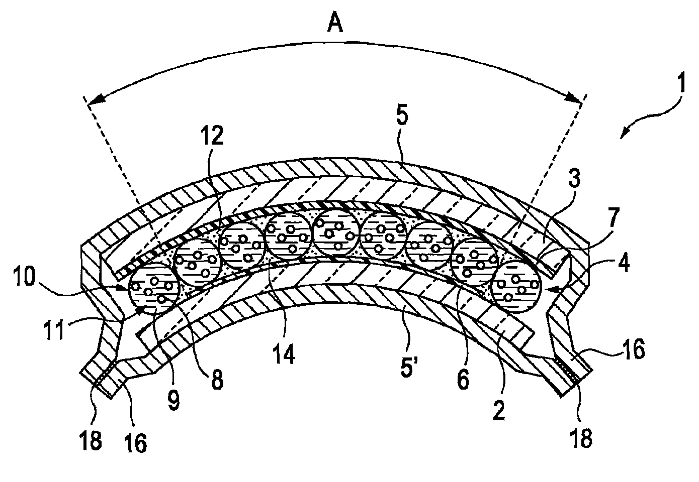
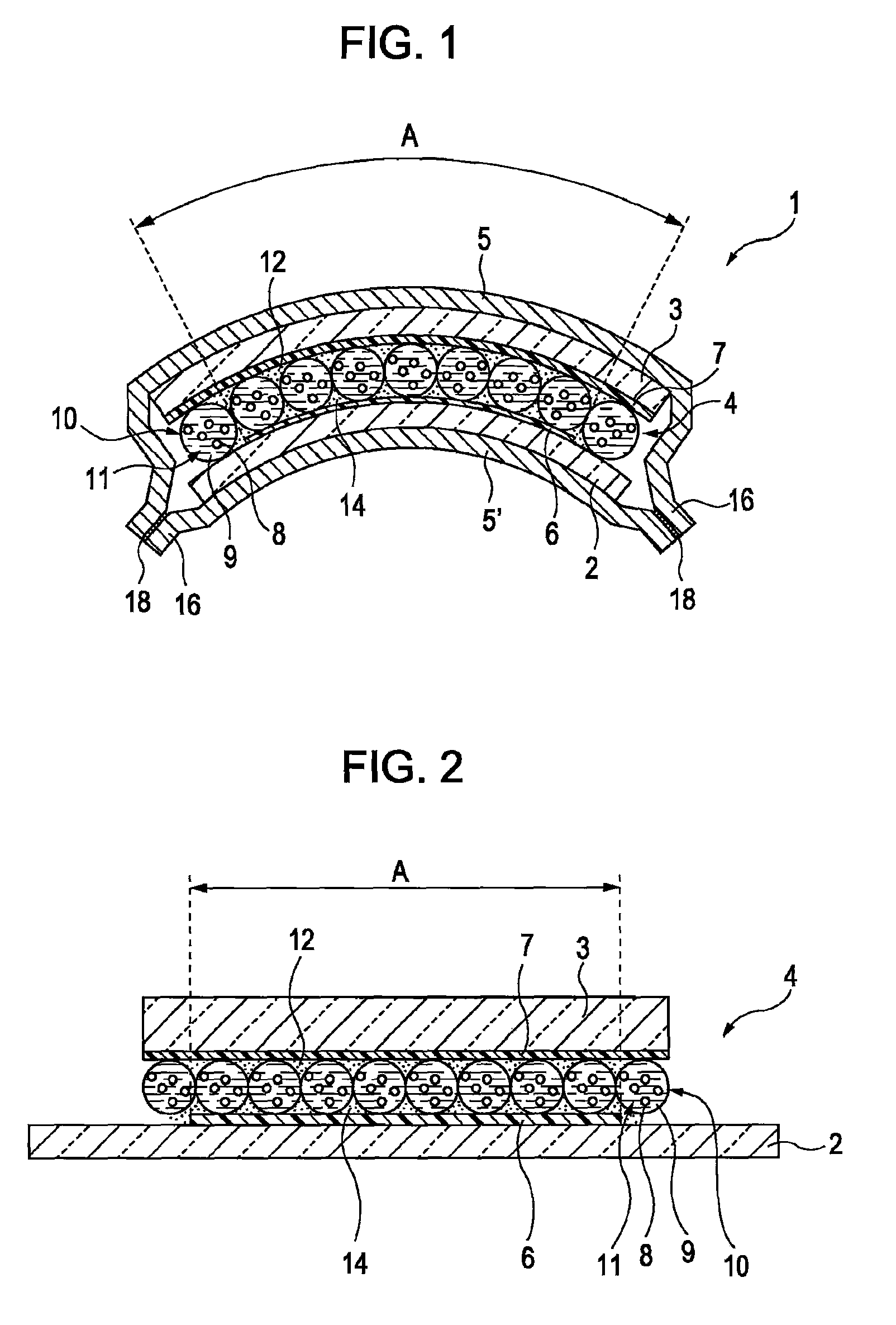
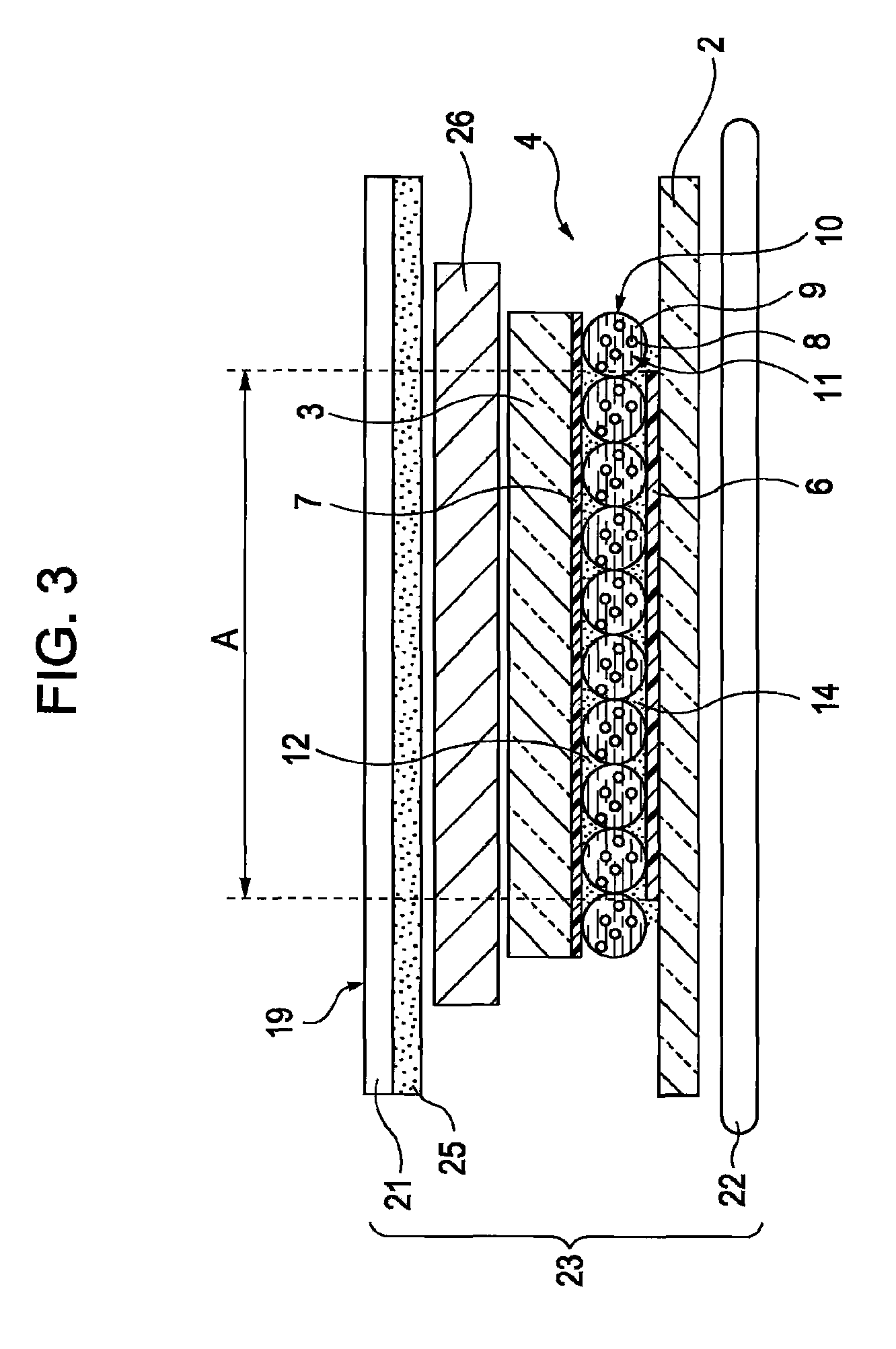
[0031]FIG. 1 shows an electro-optical device manufactured by a method according to a first embodiment of the present invention. The electro-optical device is a type of electrophoretic display. With reference to FIG. 1, the electro-optical device is represented by reference numeral 1 and is curved in side view. The electro-optical device 1 includes a first protective film 5, a second protective film 5′, and a display 4 enveloped therebetween. The display 4 includes a first substrate 2 including segment electrodes 6, a second substrate 3 including a common electrode 7, and a large number of microcapsules 10 containing an electrophoretic dispersion 11 containing a liquid dispersion medium 9 and electrophoretic particles 8. The electrophoretic dispersion 11 is a display material having optical properties varied by electrical stimulation. The electro-optical device 1 displays an image in such a manner that the distribution of the electrophoretic particles 8 is varied by applying an elect...

second embodiment

[0079]An electronic apparatus according to a second embodiment of the present invention will now be described. The electronic apparatus includes an electro-optical device manufactured by the method according to the first embodiment. Examples of the electronic apparatus are as described below.

[0080]FIG. 6 shows a wristwatch 50 that is an example of the electronic apparatus in perspective view. With reference to FIG. 6, the wristwatch 50 includes a display section 56 for displaying a time, a watch case 52 for accommodating the display section 56, and a watch belt 54 attached to the watch case 52. The display section 56 includes the electro-optical device and is curved. Therefore, the wristwatch 50 can be wound around an arm of a user.

[0081]FIG. 7 shows an electronic paper display 110 that is an example of the electronic apparatus in perspective view. The electronic paper display 110 includes a main body 111 including a rewritable sheet having the same texture and flexibility of paper ...


PUM

PropertyMeasurementUnit
diameteraaaaaaaaaa
optical propertiesaaaaaaaaaa
thicknessaaaaaaaaaa

Abstract

A method for manufacturing the following device is provided: an electro-optical device which includes a pair of substrates holding a display material having optical properties varied by electric stimulation and which has a curved shape. The method includes covering the front and rear faces of a display with a pair of protective films and then bonding end portions of the protective films to each other with an adhesive containing a thermoplastic resin, the end portions being located outside the display; heating the bonded end portions to melt the adhesive and then bending the display depending on applications; and solidifying the melted adhesive by cooling to allow the protective films to hold the display bent.

Description

BACKGROUND[0001]1. Technical Field[0002]Several aspects of the present invention relate to a method for manufacturing an electro-optical device and also relates to an electronic apparatus.[0003]2. Related Art[0004]Electrophoretic displays have been known as electro-optical devices and each contain an electrophoretic dispersion which is a display material having optical properties varied by electrical stimulation which contains a liquid dispersion medium and electrophoretic particles. The application of an electric field to the electrophoretic dispersion varies the distribution of the electrophoretic particles to vary optical properties of the electrophoretic dispersion.[0005]The electrophoretic displays require no backlights; hence, the electrophoretic displays can be manufactured at low cost and have a reduced thickness. Furthermore, the electrophoretic displays have a wide viewing angle, a high contrast ratio, and a function of holding a displayed image. Therefore, the electrophor...

Claims


Application Information

Patent Timeline
Patent Type & Authority Patents(United States)
IPC IPC(8): G09G3/34G02F1/167G02F1/16755G02F1/16757G02F1/1679
CPCG02F1/133305G02F1/133308G02F1/1341Y10T156/1002G02F2201/54G02F2202/025G02F2202/28G02F1/167G02F1/16755G02F1/16757G02F1/1679B25B27/24B25B29/00
Inventor KANBAYASHI, HATSUKI
Owner SEIKO EPSON CORP
Why Eureka
Try Eureka