Method for foaming a hydrocarbon drilling fluid and for producing light weight hydrocarbon fluids

a hydrocarbon drilling fluid and hydrocarbon technology, applied in the direction of mixing, chemistry apparatus and processes, borehole/well accessories, etc., can solve the problems of drilled solids tend to agglomerate, and underbalanced or managed drilling, so as to improve the removal of drilling fluid, stable hydrocarbon drilling fluid, and lighten the fluid column weight

Inactive Publication Date: 2010-08-03
WEATHERFORD TECH HLDG LLC
View PDF15 Cites 57 Cited by
  • Summary
  • Abstract
  • Description
  • Claims
  • Application Information

AI Technical Summary

Benefits of technology

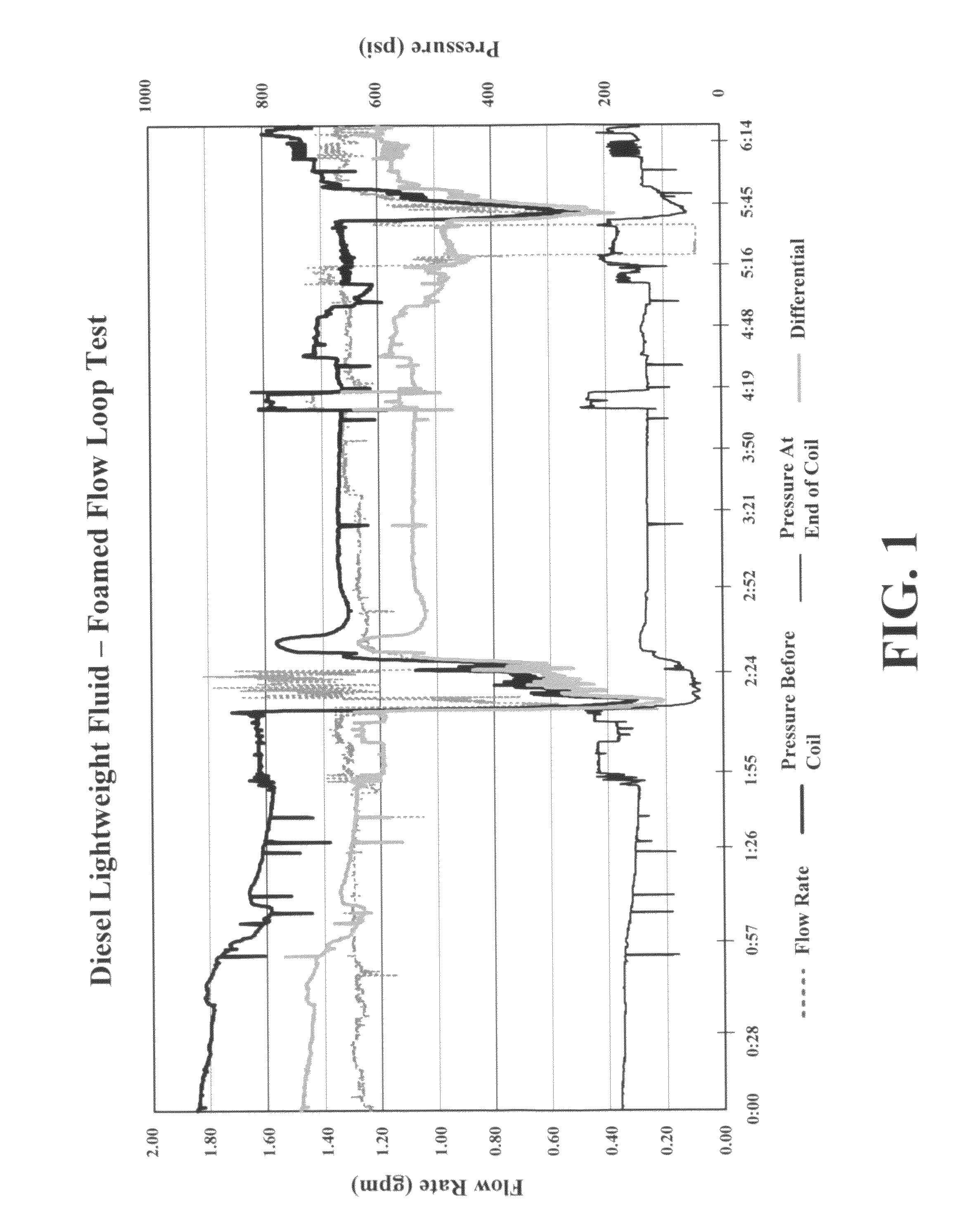
[0014]The present invention provides a method for forming a hydrocarbon drilling fluid pre-foam including the step of adding an effective amount of foaming composition to a hydrocarbon drilling fluid to form a foamable hydrocarbon drilling fluid capable of producing a more stable hydrocarbon drilling fluid foam, where the foaming composition includes a viscosifying agent and optionally a foaming agent. The viscosifying agent includes a polymer, a cross-linkable composition or mixtures or combinations thereof. The cross-linkable composition includes a gelling agent and a low concentration of a cross-linking agent. Once the foaming composition has been added to the hydrocarbon drilling fluid, a gas such as air, nitrogen, membrane nitrogen, other nitrogen / oxygen gas mixtures, carbon dioxide, an inert gas, methane, natural gas, exhaust gas, flue gas or other similar gases or mixtures or combinations thereof is added to the fluid under conditions sufficient to produce the pre-foam. The pre-foam is capable of being pumped directly into a drill string through conventional pumps without cavitation or vapor locking encountered in tradition gas-liquid combinations. When the pre-foam undergoes a pressure drop such as when it exists the drill bit, the pre-foam spontaneously converts to a foam, which lightens the fluid column weight and improves removal of the drilling fluid and the entrainment of cuttings or other materials in the well.
[0018]The present invention provides a method of drilling including the step of, while drilling, circulating a hydrocarbon drilling fluid into the borehole through the drill string. After drilling has processed to a desired extent, an oil foaming composition is injected into the hydrocarbon drilling fluid. Prior to, concurrent with or after injection of the foaming agent into the drilling fluid, a gas is injected into the fluid containing the foaming agent to produce a stable, hydrocarbon foam reducing a column weight of the drilling fluid and increasing a recirculation rate of the drilling fluid. As the drilling fluid exits the borehole at a top of the well, the foam or fluid is collected in a collector into which a defoaming agent is continuously, periodically or intermittently added to break the foam releasing the gas. Alternatively, the defoaming agent is continuously, periodically or intermittently added to the exiting foam at the wellhead causing it to break releasing the gas. After the foam has been broken releasing the gas, the fluid now including the foaming composition is recirculated into the well and refoamed via the introduction of a gas and optionally additional foaming composition if required. In one embodiment, the gas is added to the drilling fluid containing the foaming composition as it is being pumped into the drill string resulting in a lowering of a fluid weight in the drill string. As the fluid passes through the drilling bit, the fluid is disrupted resulting in the production of a stable, hydrocarbon drilling fluid foam. In one embodiment, the gas needed to produce the hydrocarbon foam is injected at the floor of the drilling platform—a traditional, but costly arrangement. In another less expensive embodiment, the gas is mixed with the fluid under pressure to produce a gasified, pre-foam fluid that is capable of being pump via conventional fluid pumps down hole, but converts into a foam upon exiting the drill bit.
[0019]The present invention also provides a method for circulating a gasified composition of this invention downhole during drilling operation. The method comprises feeding a fluid of this invention and a gas to a pressure vessel, where the gas pressures is sufficient to gasify the fluid to a desired degree and to force the fluid into and down a drill string during a drilling operation. The method also includes the step of converting the fluid to a light weight fluid as it passes through a pressure reducing orifice such as through a drill bit or a nozzle associated with the drill bit. As the fluid passes from a higher pressure to a lower pressure, the fluid spontaneously is converted into a foam. Depending on the original density of the fluid, the density of the fluid can be reduced by ½ or more. Thus, a fluid having a volume of 250 mL is converted within a second or less into a fluid having a volume of 500 mL—a 100% reduction is density. Said another way, a 7 lbs / gal fluid is converted nearly instantaneously into a 3.5 lb / gal fluid in the form of a hydrocarbon foam. The foam has greatly decreased density, has decreased frictional resistance and because it has a decreased density, lightens the fluid column weight. Moreover, the foam increases the fluid ability of entrain and hold cutting and other solids for transportation to the surface. The method also include the step of recycling the fluid exiting at the well head to the pressure vessel so that a continuously recirculating fluid system is produced. Using this type of pressure vessel arrangement would obviate the need for high pressure air injection equipment at the floor of the drilling platform, which is common practice in the industry.

Problems solved by technology

This technique is called underbalanced drilling or managed pressure drilling.
However, one difficulty in under-balanced or managed drilling where water seeps into the bore and accumulates in the drilling zone is that the drilled solids tend to agglomerate as the drill string rotates.
These agglomerated masses become too heavy to be lifted out by gas alone which leads to many drilling problem such as stick drill pipe.
Numerous foam compositions have been proposed and used under such conditions, however most have proven unsatisfactory in one respect or another.
Among the various classes of foaming compositions are nonionics; however, these are affected by salts and high temperatures encountered in drilling.
Although many anionic surfactants provide acceptable foams in soft waters, they form foam breaking precipitates in the presence of brine and / or hard water.
Cationics and zwitterionics are ineffective foamers because of their intolerance to high salinity.
Foams used with hydrocarbon based drilling fluids such as diesel or kerosene based drilling fluids are difficult to foam and if foamed, are difficult to maintain for time sufficient for circulation through the well.
However, many of these types of systems are used in conventional, over-balanced drilling.
The potential problem with a two-phase drilling fluid is once the pump rate decreases gas begins to migrate out of the fluid.
As a result, a cutting bed is established which is attributed to several drilling problem like differential sticking.

Method used


Image

  • Method for foaming a hydrocarbon drilling fluid and for producing light weight hydrocarbon fluids

Examples


example 1

[0068]This example illustrates the preparation of an illustrative example of a diluted cross-linking agent of this invention, which is then used in all of the subsequent formulations.

[0069]A cross-linking solution was prepared by adding 90 wt % of monoethylene glycol and 10 wt. % of WEC HGA-65, a ferric cross-linking agent, available from Weatherford International.

example 2

[0070]This example illustrates the preparation and testing of an illustrative example of foaming composition of this invention for foaming an oil-based drilling fluid including a foaming agent, a gelling agent and a cross-linking agent.

[0071]To 100 mL of “Off Road” Red Diesel #2 high sulfur content, 0.2 vol. % of HGA 70, a phosphate ester hydrocarbon gelling agent available form Weatherford International, and 0.5 vol. % of the solution of Example 1 were added. The resulting solution was mixed for 1 minute on Hamilton Beach Mixer at the highest speed. This solution was found to generate a foam having a foam height of 150 mL as measured in a graduated cylinder and a half life of 2:40 minutes.

[0072]To the above solution was added 0.5 vol. % of DC-1250, a foaming agent available from Dow Corning, and the resulting solution was mixed for 1 minute on Hamilton Beach Mixer at the highest speed. The solution was found to generate a foam having a foam height of 170 mL and a half life of 5:15 ...

example 3

[0076]This example illustrates the preparation and testing of another illustrative example of a foaming composition of this invention for foaming an oil-based drilling fluid.

[0077]To 100 mL “OffRoad” Red Diesel #2, 0.2 vol. % HGA 70, a phosphate ester gelling agent available from Weatherford International, and 0.5 vol. % of the cross-linking solution of Example 1 were added. The solution was mixed for 1 minute on Hamilton Beach Mixer at the highest speed. To this solution was added 0.5 vol. % Zonyl FSG, a foaming agent available from DuPont with mixing for 1 minute on Hamilton Beach Mixer at the highest speed. The foamed solution had a foam height of 170 mL and a half life of 6:00 minutes.

[0078]To this solution was added 10 vol. % of crude oil as a contaminant with mixing for 1 minute on Hamilton Beach Mixer at the highest speed to produce a foam having a foam height of 180 mL with a half life of 2:00 minutes.

[0079]From Examples 2 and 3, the addition of crude oil to the drilling flu...


PUM

PropertyMeasurementUnit
volumeaaaaaaaaaa
volumeaaaaaaaaaa
volume percentaaaaaaaaaa

Abstract

A hydrocarbon drilling fluid system is disclosed including a hydrocarbon fluid and a foaming composition, where the foaming composition includes a polymer, a gelling agent and its cross-linking agent, an optional foaming agent, or mixtures or combinations thereof. Uses of this drilling fluid system in a variety of downhole application are also disclosed.

Description

BACKGROUND OF THE INVENTION[0001]1. Field of the Invention[0002]The present invention relates to a method for drilling, completing, producing, fracturing and stimulating a gas and / or oil well using a hydrocarbon fluid compositions having improved foaming properties, improved gas retention properties, and improved pumping properties. The invention also relates to methods for making the compositions and to compositions.[0003]More particularly, the present invention relates to a method for producing a stable, hydrocarbon drilling fluid foam, where the method includes the step of pumping a pre-gasified, foamable hydrocarbon drilling fluid into a drilling string and / or a borehole of a well during drilling operations. As the fluid passes through a drill bit at the end of the drill string and into the well, the fluid changes from a pre-gasified, foamable hydrocarbon drilling fluid into a stable hydrocarbon drilling foam resulting in a decrease in column weight of the fluid in and an increa...

Claims


Application Information

Patent Timeline
Patent Type & Authority Patents(United States)
IPC IPC(8): C09K8/38E21B21/14
CPCC09K8/36C09K8/38C09K8/703C09K8/94C09K8/60
Inventor KIPPIE, DAVID P.GATLIN, LARRY W.
Owner WEATHERFORD TECH HLDG LLC
Why Eureka
Try Eureka