Particle therapy system

a technology of particle therapy and particle therapy, applied in the field of particle therapy system, can solve the problems of more complex control procedures and achieve the effect of reducing the risk of collision

Active Publication Date: 2010-08-03
SIEMENS HEALTHCARE GMBH
View PDF28 Cites 43 Cited by
  • Summary
  • Abstract
  • Description
  • Claims
  • Application Information

AI Technical Summary

Benefits of technology

[0009]In one embodiment, the C-arm is mounted on the wall of the irradiation room in such a way that it also rotates in conjunction with rotation of the gantry. The C-arm may be connected to the gantry in such a way that in a rest position, in which it does not intersect the trajectory of the irradiation unit, it rotates along with the gantry. Control of the C-arm may be significantly facilitated, since in the retracted parking position it need not be readjusted relative to the further gantry components.
[0015]To reduce the risk of a collision with the outlet aperture of the irradiation unit, the C-arm is attached in a pivotable manner. The C-arm, in the extended position, may be arranged inclined to the vertical. Due to the inclined position of the C-arm, the imaging unit includes a further degree of freedom in its positioning for imaging purposes. As a result of the inclination, the movement levels of the C-arm and the irradiation unit differ so much from each other that a collision is avoided.

Problems solved by technology

In this case, more complex control procedures are required, so that in the event of an impending collision between the irradiation unit and the C-arm this is diverted in a timely manner.

Method used


Image

  • Particle therapy system
  • Particle therapy system
  • Particle therapy system

Examples


Embodiment Construction

[0022]In the figures, parts operating in a similar manner are identified by identical reference numbers.

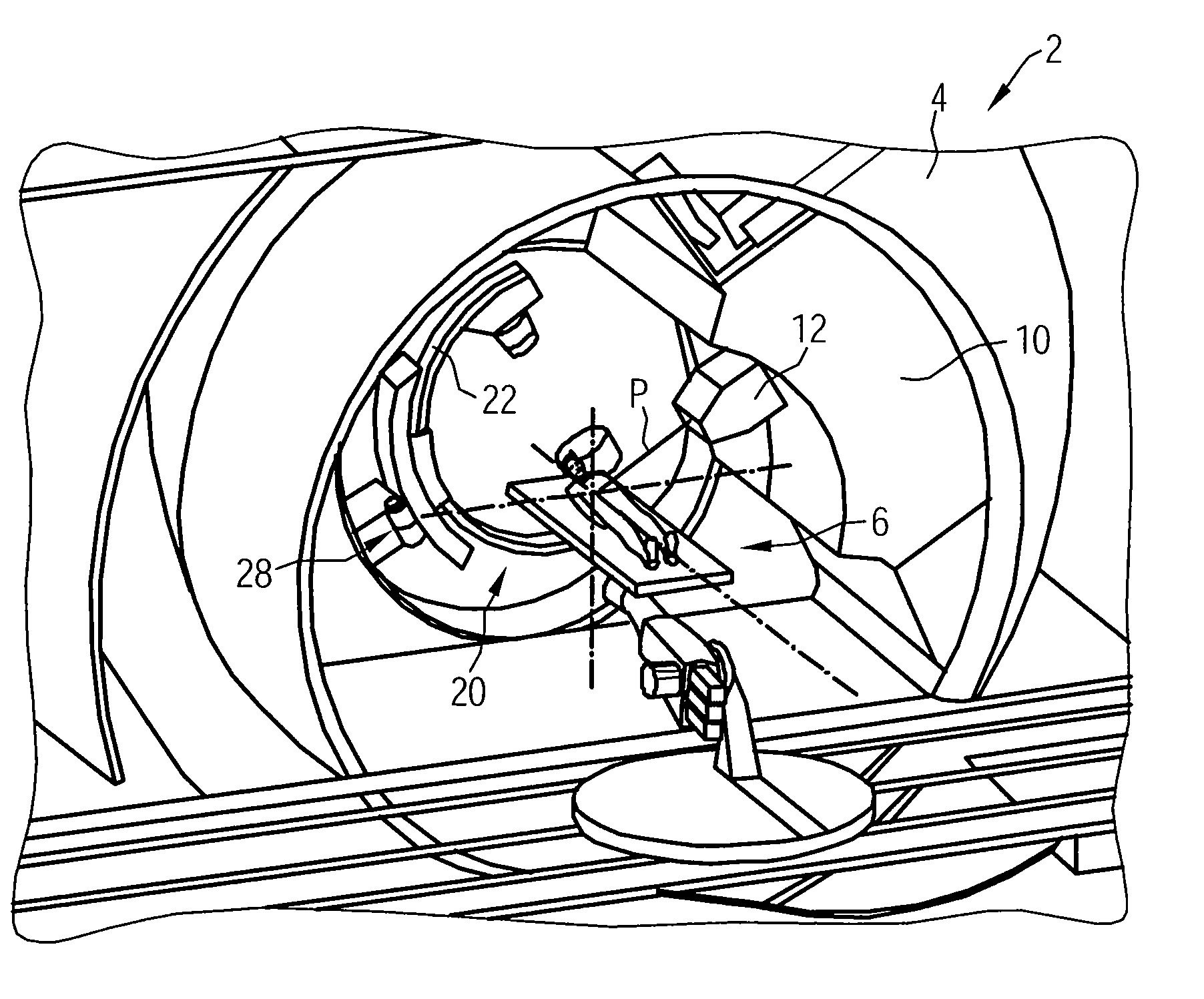
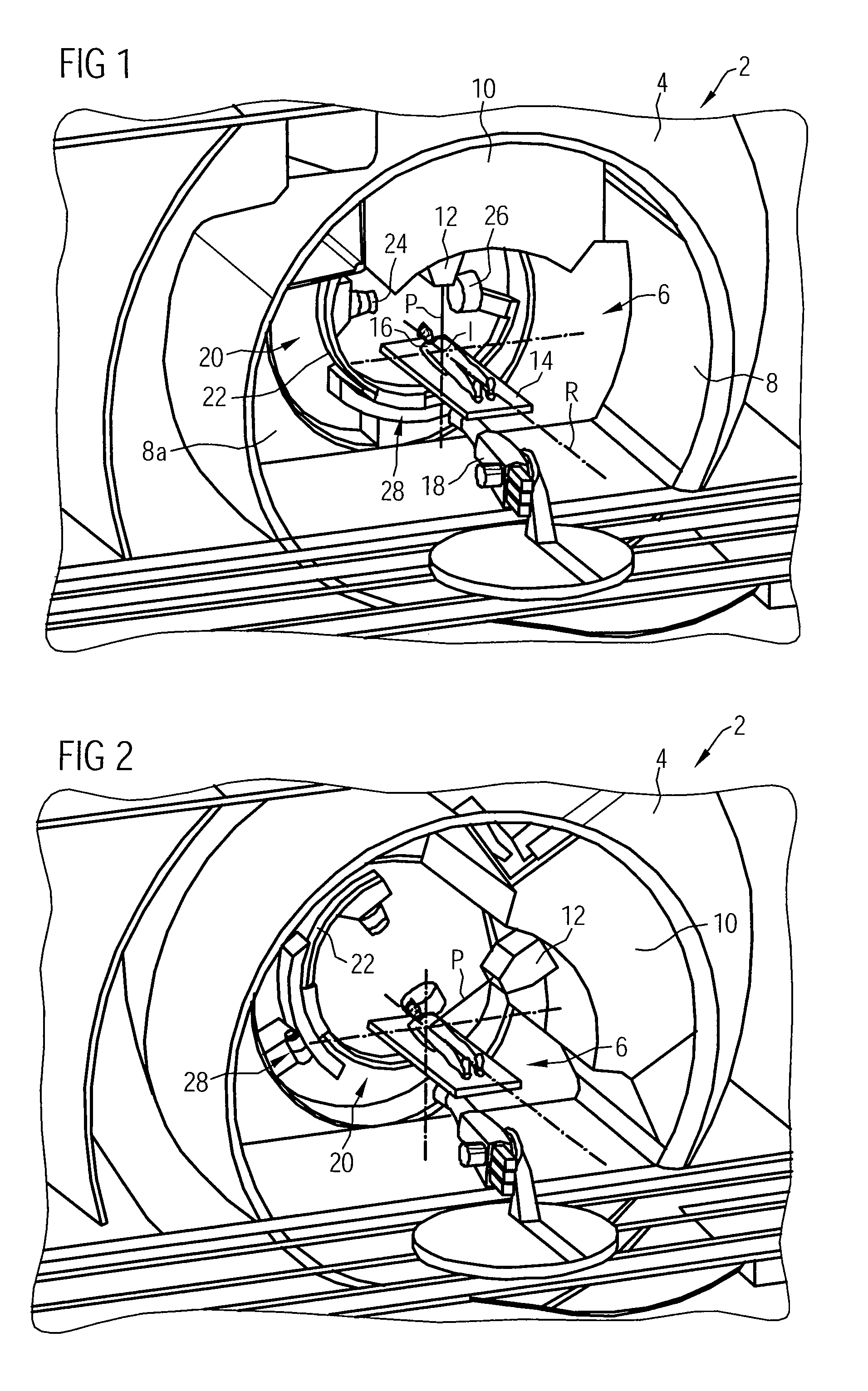
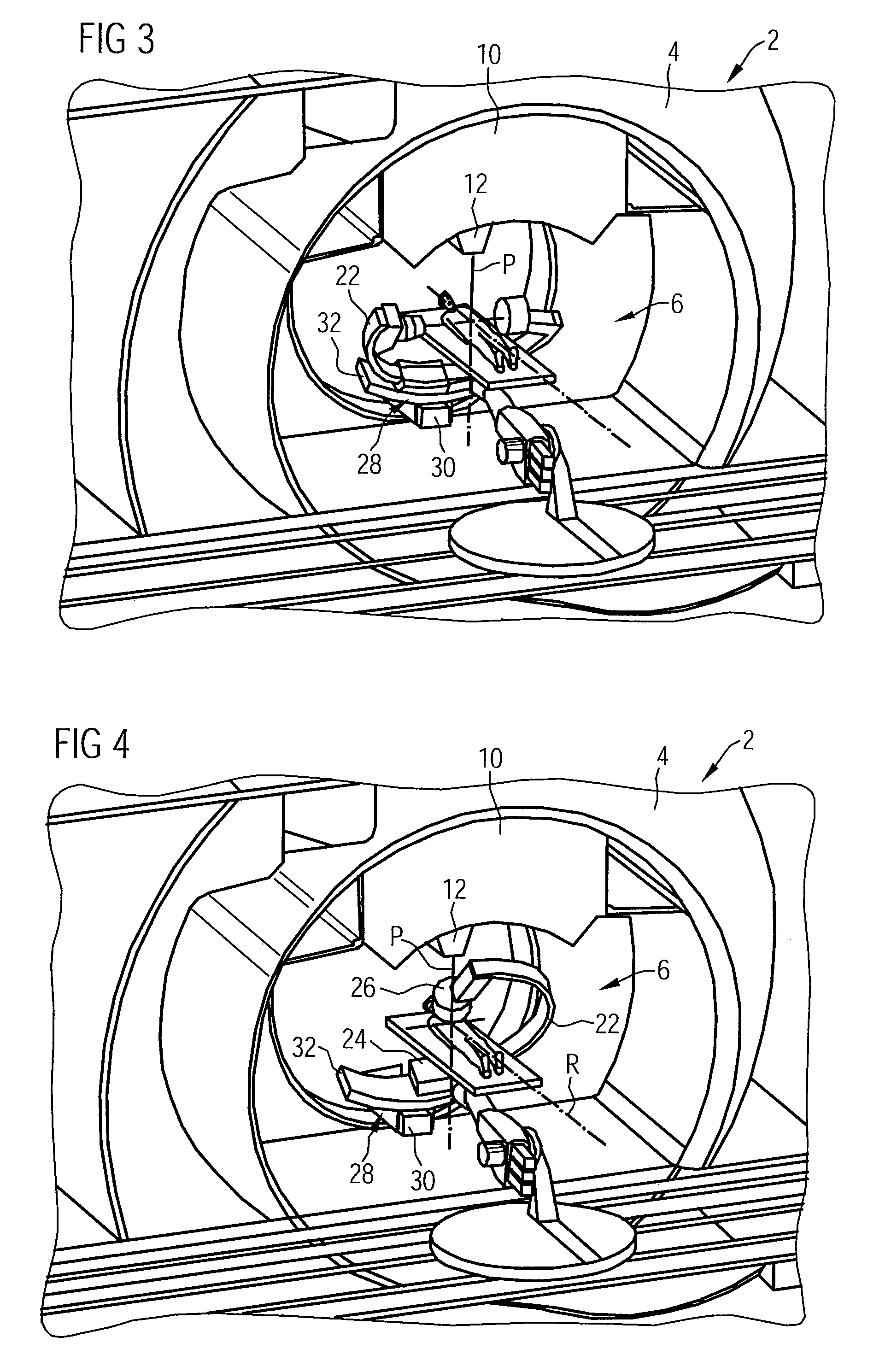
[0023]FIG. 1 shows a particle therapy system 2. The particle therapy system 2 includes a rotatable gantry 4, which can be rotated through 360° around an axis of rotation R. The gantry 4 may include a cylindrically embodied irradiation room 6, which is delimited by a wall 8. The gantry 4 includes an irradiation unit 10, from which an outlet aperture 12 projects into the irradiation room 6. A particle beam P, for example, an ion or proton beam, for the treatment of a patient 16 lying on a patient couch (support) 14, is guided in an irradiation channel of the gantry 4. The particle beam P enters the irradiation room 6 via the outlet aperture 12.

[0024]The patient couch 14 is positioned in the irradiation room 6 by a patient handling system, such as a controlled robot 18. The patient couch 14 is positioned in such a way that the tissue of the patient 16 to be irradiated lies in an isoc...


PUM


Abstract

A particle therapy system is provided. The particle therapy system includes an imaging unit and a rotatable gantry with an irradiation unit. The irradiation unit projects into an irradiation room delimited by a wall. The imaging unit is arranged on a C-arm. The C-arm is operable to be moved between a retracted parking position and an extended diagnostic position for imaging purposes.

Description

[0001]The present patent document claims the benefit of the filing date of DE 10 2007 042 340.5, filed Sep. 6, 2007, which is hereby incorporated by reference.BACKGROUND[0002]The present embodiments relate to a particle therapy system including a rotatable gantry with an irradiation unit, which projects into an irradiation room delimited by a wall.[0003]Particle therapy may be used to treat cancers. During particle therapy, a particle beam, for example, composed of protons or ions, is generated in an accelerator. The particle beam is guided in an irradiation channel and enters an irradiation room via an outlet aperture of an irradiation unit.[0004]The gantry includes an approximately cylindrical irradiation room into which a patient couch is introduced. For precise treatment, the tissue of the patient to be irradiated (e.g., the tumor) is positioned as exactly as possible in the isocenter of the system. An imaging system is used to verify the position of the tumor. The imaging syste...

Claims


Application Information

Patent Timeline
Patent Type & Authority Patents(United States)
IPC IPC(8): A61N5/10A61N5/00
CPCA61N5/1049A61N5/1081A61N2005/1061A61N2005/1087
Inventor KAISER, WERNERSUST, EBERHARD
Owner SIEMENS HEALTHCARE GMBH
Why Eureka
Try Eureka