Current resonant DC-DC converter of multi-output type
a dc-dc converter and multi-output technology, applied in the direction of electric variable regulation, process and machine control, instruments, etc., can solve the problems of reducing the output voltage produced in the other side of the second winding, and achieve the effects of improving power conversion efficiency, high accuracy, and prolonging the service life of related elements
- Summary
- Abstract
- Description
- Claims
- Application Information
AI Technical Summary
Benefits of technology
Problems solved by technology
Method used
Image
Examples
first embodiment
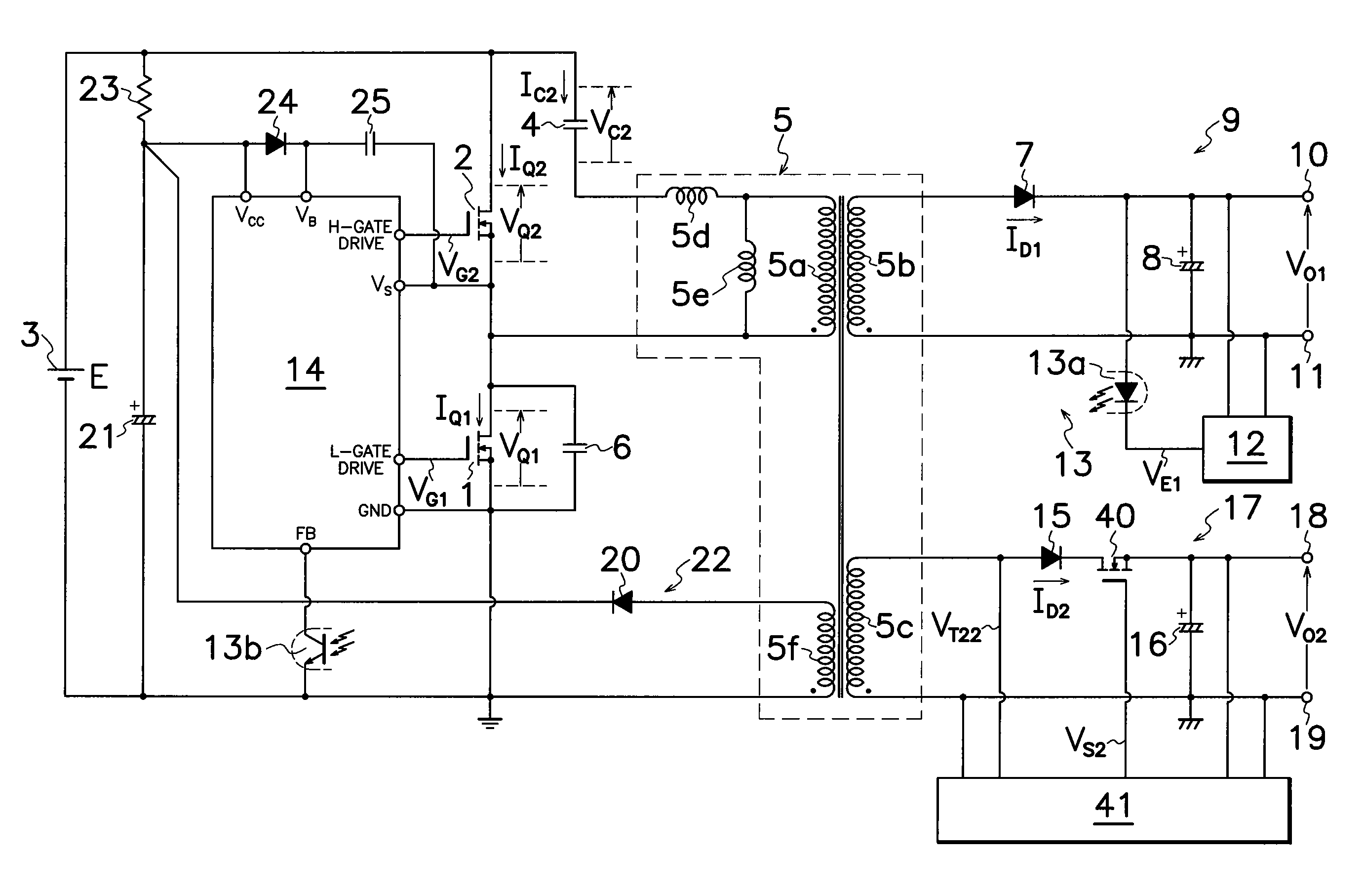
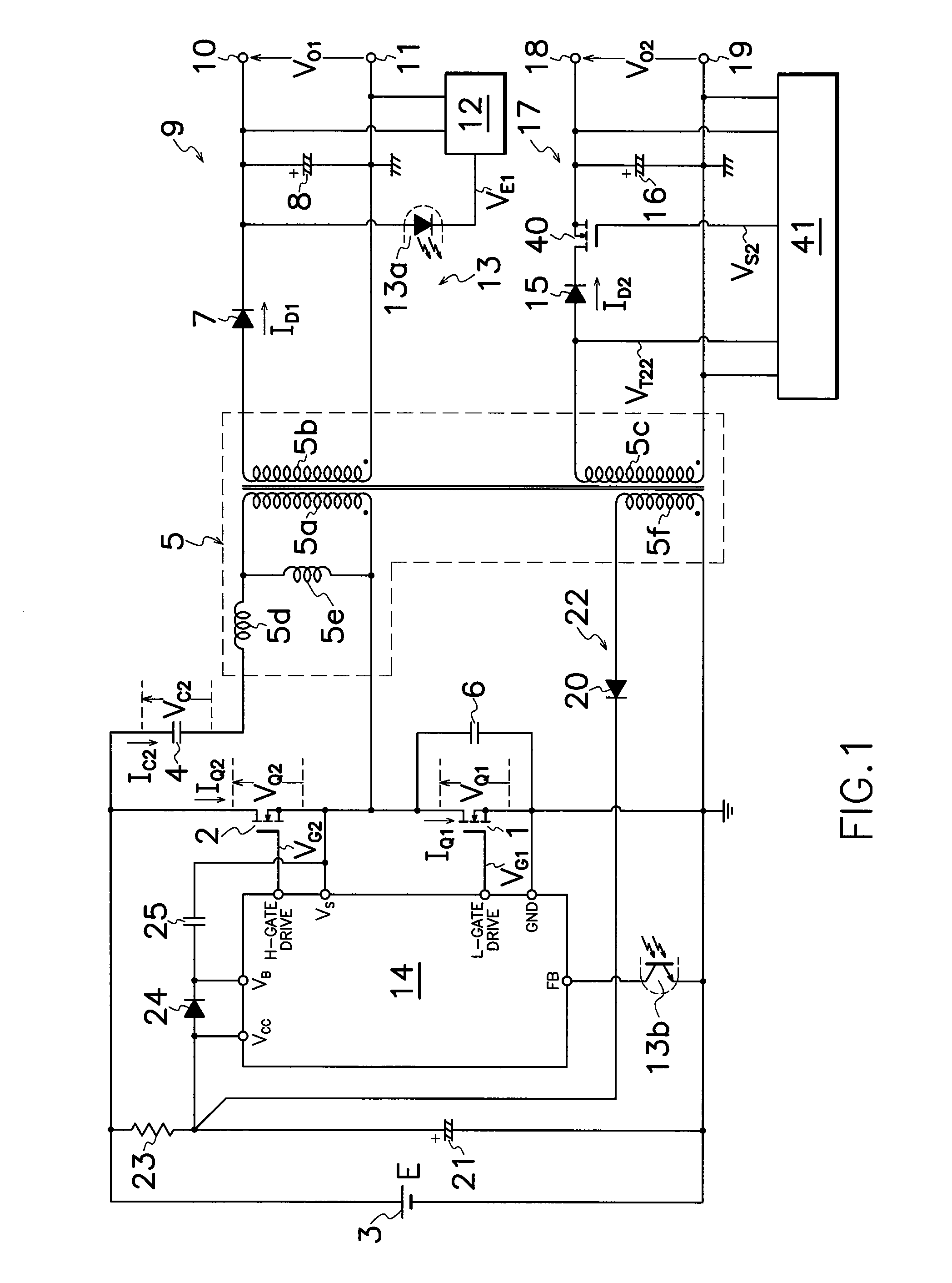
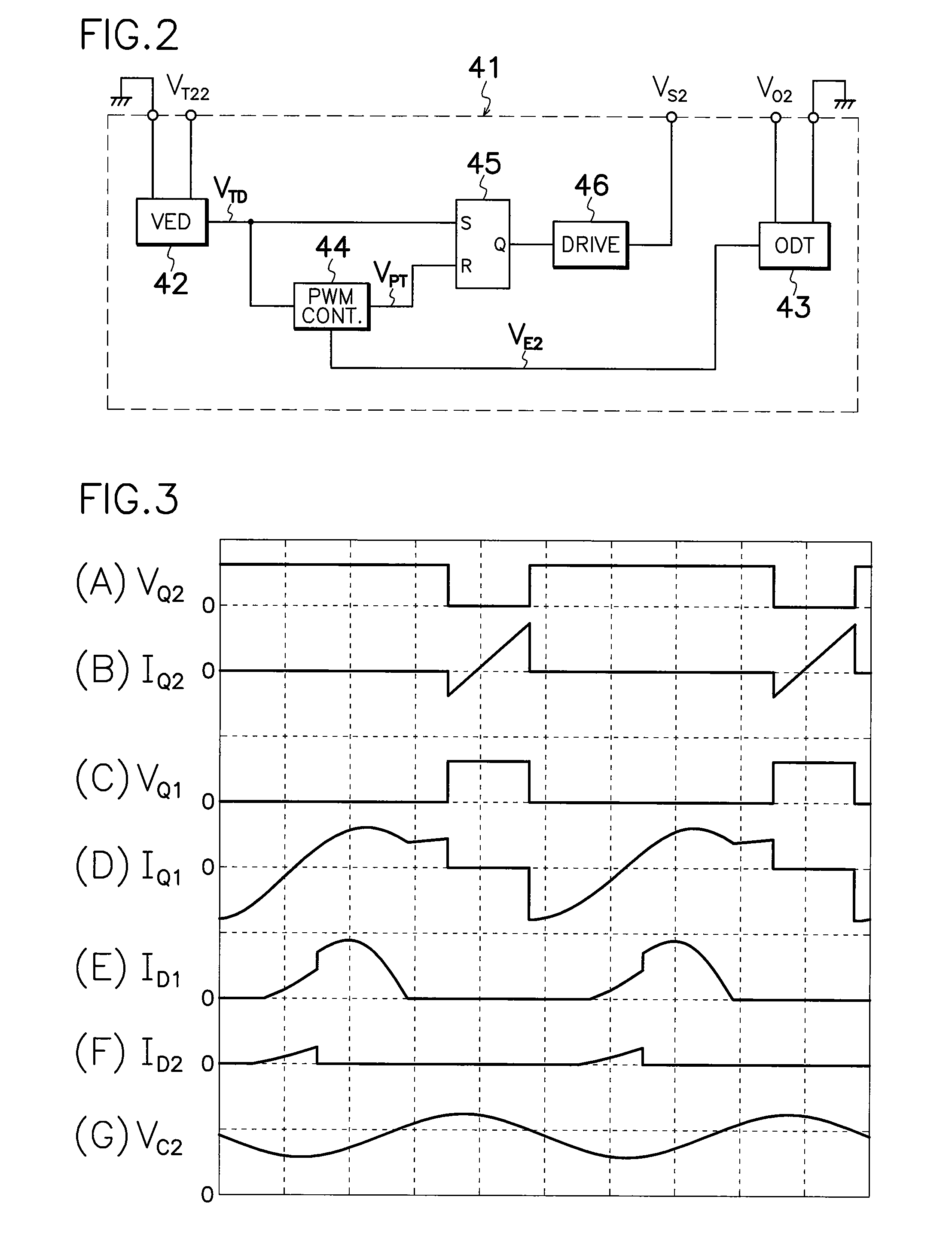
[0064]FIG. 1 illustrates an electric circuit diagram of a first embodiment according to the present invention's current resonant DC-DC converter of multi-output type which comprises an output-regulatory MOS-FET 40 as an output-regulatory switching element connected between a cathode terminal of second output rectifying diode 15 in second rectifying smoother 17 and second output smoothing capacitor 16, and an output control circuit 41 connected to second DC output terminals 18 and 19 and a gate terminal of output-regulatory MOS-FET 40 for controlling the on-off operation of MOS-FET 40 based on voltage VO2 in second output rectifying capacitor 16, while omitting stepdown chopper 30 and chopper controller 31 shown in FIG. 35. In operation, output-regulatory MOS-FET 40 is turned on and off with the same switching frequency of first main MOS-FET 1 and in synchronization with the on-period of first main MOS-FET 1. Simultaneously, main control circuit 14 produces drive signals VG1 and VG2 ...
second embodiment
[0072]The DC-DC converter shown in FIG. 1 can be modified in various ways. For example, the current resonant DC-DC converter of multi-output type according to the present invention comprises a third secondary winding 5g as an additional secondary winding provided in transformer 5 shown in FIG. 4, a third rectifying smoother 49 as an additional rectifying smoother which comprises a third output rectifying diode 47 and a third output smoothing capacitor 48 connected to third secondary winding 5g, an additional output-regulatory MOS-FET 50 as an additional switching element connected between a cathode terminal of third output rectifying diode 47 and third output smoothing capacitor 48, and an additional control circuit 53 for controlling the on-off operation of additional output-regulatory MOS-FET 50 based on the level of voltage VO3 on third output smoothing capacitor 48 connected between third DC output terminals 51 and 52 and additional output-regulatory MOS-FET 50. Third secondary ...
fourth embodiment
[0076]the current resonant DC-DC converter of multi-output type shown in FIG. 6 according to the invention, comprises output-regulatory MOS-FET 40 moved from a positive line shown in FIG. 4 to a ground line between second secondary winding 5c of transformer 5 and second output smoothing capacitor 16, third secondary winding 5g of transformer 5 provided in the adverse polarity to FIG. 4, and third output rectifying diode 47 moved from positive line of FIG. 4 to ground line between third secondary winding 5g of transformer 5 and third output smoothing capacitor 48. Other configurations are similar to those in the DC-DC converter shown in FIG. 4, and operation of the converter shown in FIG. 6 is substantially similar to that in the converter shown in FIG. 1.
[0077]The converter shown in FIG. 6 can attain the almost unchanged period of supplying electric energy from primary to secondary side of transformer 5 although load fluctuates, while obtaining similar functions and effects to those...
PUM
 Abstract
Description
Claims
Application Information
 - R&D
- Intellectual Property
- Life Sciences
- Materials
- Tech Scout
- Unparalleled Data Quality
- Higher Quality Content
- 60% Fewer Hallucinations
Browse by: Latest US Patents, China's latest patents, Technical Efficacy Thesaurus, Application Domain, Technology Topic, Popular Technical Reports.
© 2025 PatSnap. All rights reserved.Legal|Privacy policy|Modern Slavery Act Transparency Statement|Sitemap|About US| Contact US: help@patsnap.com


