Method and system for reducing noise level in a video signal

Inactive Publication Date: 2010-08-03
CORONA
View PDF15 Cites 58 Cited by
  • Summary
  • Abstract
  • Description
  • Claims
  • Application Information

AI Technical Summary

Benefits of technology

[0015]Nonetheless, a noise reduction system that performs both spatial and temporal noise reduction operations requires pixel and/or line buffers as well as frame/field buffers. Frame/field buffers are particularly costly and also increase the complexity of the system. Moreover, reading and writing video field pixel data from and to the frame/field buffers consume system resources, such as memory bandwidth and power consumption. Thus, while desirable, such a system is less economically feasible.
[0016]In one embodiment, a method of reducing noise levels in an input video signal comprising pixel data includes receiving input pixel data of the input video signal, where the input pixel data comprises luminance data and chrominance data, and estimating a noise level of the input video signal using the luminance data of the input pixel data. A plurality of filter parameters are identified based on the estimated noise level, and the input pixel data is filtered using a three dimensional spatiotemporal noise reduction filter that is controlled by a first set of the plurality of filter parameters. Thereafter, the method includes filtering the filtered input pixel data using a one dimensional temporal noise reduction filter with motion compensation that is controlled by a second set of the plurality of filter parameters, and generating a noise-filtered output video signal that includes the filtered input pixel data from the three dimensional spatiotemporal noise reduction filter and the motion compensated filtered input pixel data from the one dimensional temporal noise reduction filter.
[0017]In another embodiment

Problems solved by technology

While this technique has the benefits described above, the use of interlacing can also lead to the appearance of visual artifacts such as line flicker for stationary objects and line crawling for moving objects.
As stated above, if the interlaced video signal 29 is displayed, undesirable visual artifacts, such as line flicker and line crawling, exist.
These methods, however, do not necessarily take into consideration motion between video fields.
For instance, it is well known that while line repetition may be acceptable for image regions having motion, line repetition is not suitable for stationary (still) image regions due to loss of vertical spatial resolution.
By the same token, field insertion is a satisfactory de-interlacing method for stationary image regions, but inadequate for moving image regions due to objectionable motion artifacts.
Therefore, utilizing one method presents a tradeoff between vertical spatial resolution and motion art

Method used


Image

  • Method and system for reducing noise level in a video signal
  • Method and system for reducing noise level in a video signal
  • Method and system for reducing noise level in a video signal

Examples


Embodiment Construction

[0032]The present invention relates in general to digital image and video signal processing and in particular to a digital signal processing method and system for automatically reducing the noise level in an input video signal. The following description is presented to enable one of ordinary skill in the art to make and use the invention and is provided in the context of a patent application and its requirements. Various modifications to the preferred embodiments and the generic principles and features described herein will be readily apparent to those skilled in the art. Thus, the present invention is not intended to be limited to the embodiments shown, but is to be accorded the widest scope consistent with the principles and features described herein.

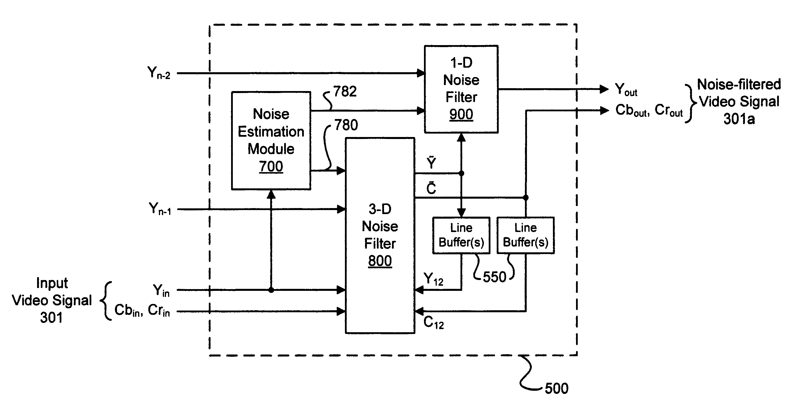
[0033]According to an embodiment of the present invention, a three dimensional spatiotemporal noise reduction module is integrated with a motion detection system, such as that described in the co-pending patent application Ser. No. 11...


PUM


Abstract

A method of reducing noise levels in an input video signal comprising pixel data includes receiving input pixel data of the input video signal, where the input pixel data comprises luminance data and chrominance data, and estimating a noise level of the input video signal using the luminance data of the input pixel data. A plurality of filter parameters are identified based on the estimated noise level, and the input pixel data is filtered using a three dimensional spatiotemporal noise reduction filter that is controlled by a first set of the plurality of filter parameters. Thereafter, the method includes filtering the filtered input pixel data using a one dimensional temporal noise reduction filter with motion compensation that is controlled by a second set of the plurality of filter parameters, and generating a noise-filtered output video signal that includes the filtered input pixel data from the three dimensional spatiotemporal noise reduction filter and the motion compensated filtered input pixel data from the one dimensional temporal noise reduction filter.

Description

RELATED PATENT APPLICATIONS[0001]The present application is a continuation-in-part application of patent application entitled METHOD AND SYSTEM FOR DETECTING MOTION BETWEEN VIDEO FIELD OF SAME AND OPPOSITE PARITY FROM AN INTERLACED VIDEO SOURCE (Ser. No. 11 / 001,826), filed on Dec. 2, 2004 now U.S. Pat. No. 7,616,693 and assigned to the assignee of the present invention.FIELD OF THE INVENTION[0002]The present invention relates in general to digital image and video signal processing and in particular to a digital signal processing method and system for automatically reducing the noise level in an input video signal.BACKGROUND OF THE INVENTION[0003]The NTSC, PAL, and SECAM analog television standards and the ITU-R BT.601 and ITU-R BT.709 digital video television standards are in widespread use throughout the world today. All of these standards make use of interlacing video signals in order to maximize the vertical refresh rate, which reduces wide area flicker, while minimizing the band...

Claims


Application Information

Patent Timeline
IPC IPC(8): H04N7/12
CPCH04N5/144H04N5/21H04N7/012
Inventor CHOU, CHIH-HSIEN
Owner CORONA
Why Eureka
Try Eureka