Turbofan arrangement

a technology for aerospace turbofans and turbine stages, which is applied in the direction of machines/engines, hot gas positive displacement engine plants, engine manufacture, etc., can solve the problems of increasing the mean diameter or stage load of the turbine, increasing the duct length and duct loss between the compressors, and increasing the number of turbine stages. , to achieve the effect of improving the design of known multiple fan engines and increasing the mean diameter or stage load

Inactive Publication Date: 2010-08-10
ROLLS ROYCE PLC
View PDF16 Cites 54 Cited by
  • Summary
  • Abstract
  • Description
  • Claims
  • Application Information

AI Technical Summary

Benefits of technology

[0013]The present invention improves the design of known multiple fan engines, avoiding or greatly reducing all the previously described disadvantages of the aforementioned engine arrangements. Relative to a conventional engine of a given overall bypass ratio it can halve the total number of turbine stages required to drive the fans, without increasing turbine mean diameter or stage loading or using a gearbox.
[0016]Preferably, the engine is arranged so that the airflow from the core compressor flows through the heat exchanger and into the combustor, the fluid flow from the combustor drivingly flows through the core turbine, the first turbine and the heat exchanger thereby increasing the heat of the airflow from the core compressor to the combustor.
[0021]Additionally, the engine further comprises a first chamber and a second heat exchanger, the first chamber is located between and is in fluid communication with the first fan and the core compressor the second heat exchanger is adjacent the first chamber and is arranged to receive fluid from the second compressor through the heat exchanger, cooling fluid from the first fan passes through the heat exchanger to cool the fluid from the second compressor so that the core compressor compresses the fluid more efficiently. In this embodiment, the second heat exchanger comprises valves, operable to open and close the second heat exchanger to fluid flows from the first fan and the second compressor so that, in use, a desirable increase in engine power is achieved when the valves are closed and the engine is more efficient when the valves are open. Further, the fluid passing through the heat exchanger from the first fan is ducted to and mixed with a fluid flow exhausting from the turbine and upstream of the final nozzle.

Problems solved by technology

The increased fan shaft diameter increases the minimum bore diameters of the core components, requiring them to be designed for lower rotational speeds that, in turn, increase parts counts, cost and weight.
The increased bypass ratio also results in a mismatch between the hub radius of the fan and the hub radius of the subsequent compressor stages, increasing duct lengths and duct losses between compressors.
The higher bypass ratio also requires an increased number of turbine stages to drive the fan, the maximum turbine radius being limited by installation constraints.
Very high bypass ratio engines are prohibitively heavy, and when installed under-wing on a conventional low wing aircraft they require an increase in aircraft undercarriage length which adds further cost and weight penalties to the aircraft.
The larger size engines are also more difficult to transport to and from the aircraft.
However this arrangement adds the cost, mass, complexity and potential unreliability of incorporating a high power gearbox, it is unproven for large engines, and is unattractive to aircraft operators.
Problems still remain with the mismatch in compressor hub radii and with the installation of the engine on the aircraft.
Small engines are however less efficient and less cost effective than large engines and this arrangement does not solve the problem that each engine needs either a very large number of turbine stages or a geared fan.
However, the convoluted exit nozzles for the first fan and the bifurcated intakes for the second fan add significantly to the installation losses for a low specific thrust version of such an engine.
In a conventional under-wing installation the extra length of a tandem fan engine projecting forwards from under the wing results in higher wing bending moments and a significant weight penalty for the wing and the pylon supporting the engine.
The forward extension of the engine also interferes with the space available for loading and unloading the aircraft.
These arrangements have the disadvantage of needing complex geared drive systems.
However, tip turbines are not easy to design and manufacture, and sealing them is particularly difficult.
Gas leakages result in poor performance, making such arrangements unattractive.
Such engines need additional combustors that add to the complexity and potential unreliability of the engines, making them unattractive.
The disadvantages of this multiple fan engine arrangement, for a low specific thrust engine, are that a very large number of turbine stages are required; the core intake is not protected from ingestion of foreign objects by an upstream fan; the core needs its own intake with its additional pressure losses; and the core compressors do not benefit from the supercharging of the air through a fan.
None of these previously described designs is entirely satisfactory for a very low specific thrust engine mounted in an under-wing installation.

Method used


Image

  • Turbofan arrangement
  • Turbofan arrangement
  • Turbofan arrangement

Examples


first embodiment

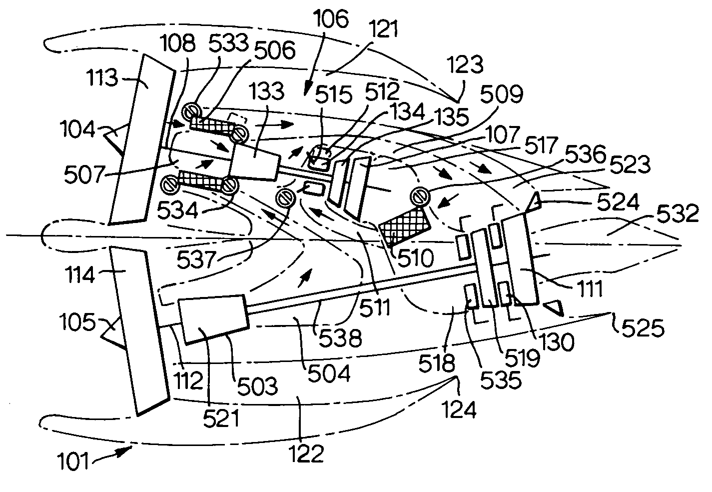
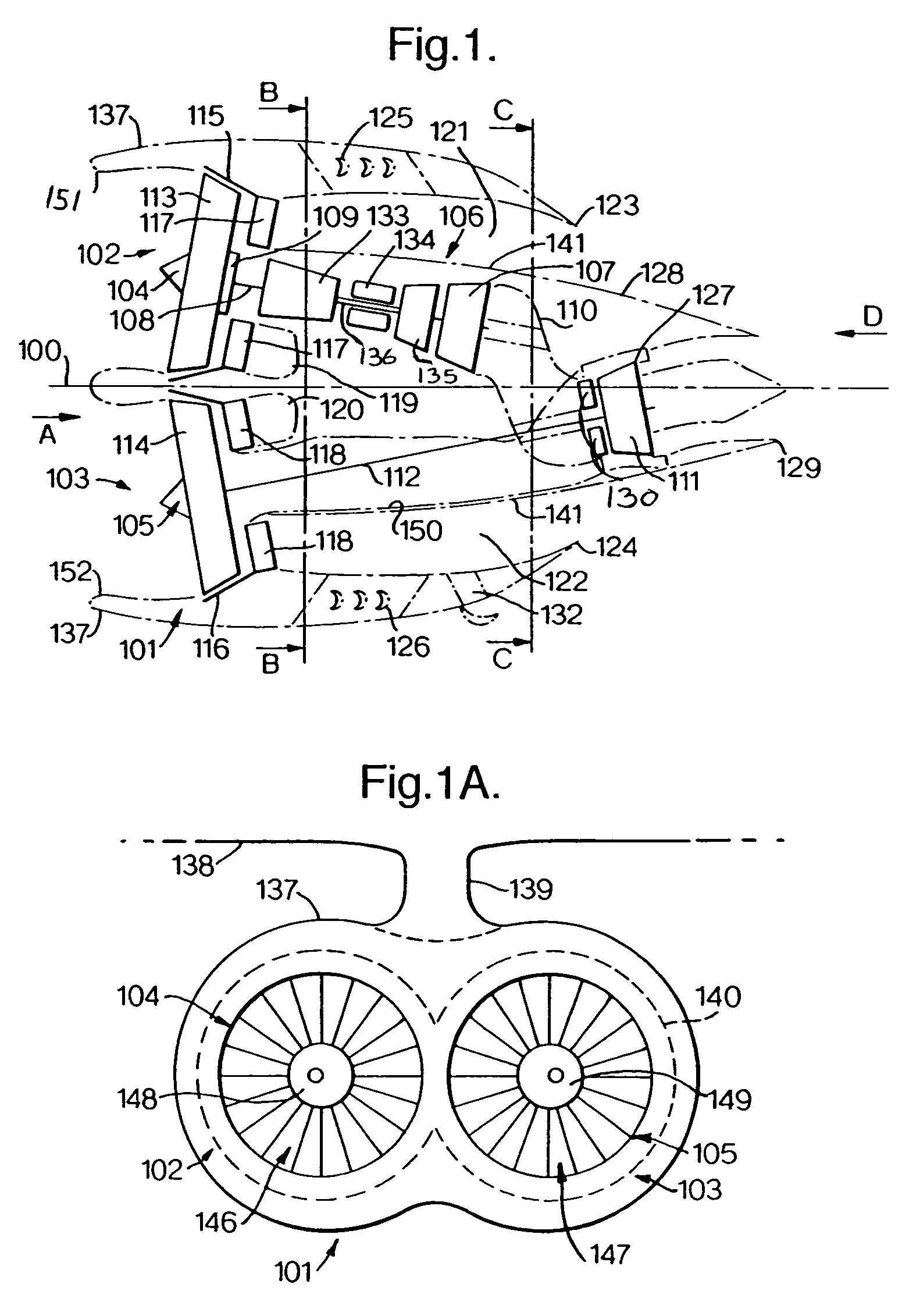
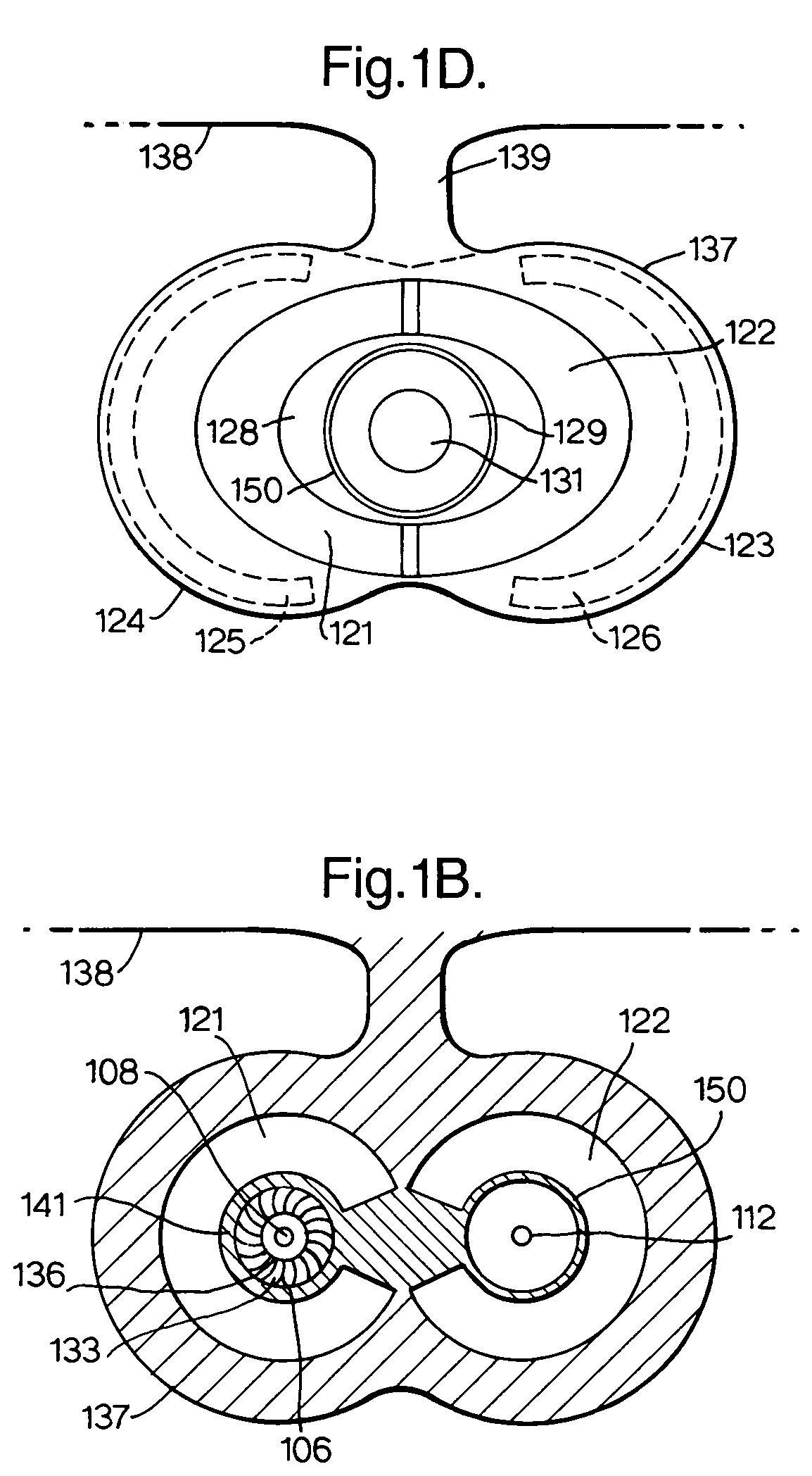
[0050]With reference to FIG. 1, the turbofan engine 101 is a low specific thrust engine 101 configured with first and second propulsion systems 102, 103 comprising first and second fan systems 104 and 105 respectively that are disposed equi-angularly about a centre-line 100. The first and second fan systems 104 and 105 each comprise a first and second fan rotor 113, 114 respectively and are mounted generally side by side, when installed on an aircraft wing that is generally horizontal, in an integrated nacelle 137. The nacelle 137 comprises two intake systems 151 and 152. The fan systems 104 and 105, in use, are co-rotating to maximise parts commonality. Alternatively, the fan systems 104 and 105 are arranged to contra-rotate, thereby minimising gyro-couples and maximising turbine efficiencies. The first fan system 104 has a conventional bypass ratio η1 and is followed, in the downstream flow direction, by a conventional core engine or gas generator 106 coaxial to the first fan syst...

second embodiment

[0075]FIG. 2 shows a turbofan engine 201, generally similar in configuration to the turbofan engine 101 described with reference to FIG. 1, except that synchronisation of the speeds of the fan rotors 113 and 114 and controlling the fan working lines at least partly is by means of variable bleed flows 204 and 205 from the two bypass ducts 121 and 122 respectively. These bypass duct bleed flows 204, 205 are exhausted together with the exhaust gasses from the final turbine 111 through a variable area mixed flow exhaust nozzle 209. The bleed flows from bypass ducts 121 and 122 are regulated by means of one or more variable geometry flow off-takes 210 and 211. Alternatively, bleed flows through the off-take ducts 210, 211 are modulated by means of a variable area mixer assembly 212. The variable area mixer assembly 212 is configured to vary the pressure ratio in the exhaust nozzle 209 thereby increasing or decreasing flow through the ducts 210, 211 as required.

[0076]It should be apprecia...

fifth embodiment

[0086]the present invention is easily appreciable and one which would be most appropriate for a very large and very high bypass ratio engine has a cluster of five, approximately coplanar, parallel flow fans 101, 103, 453, 454 and 455, disposed in a “W” or “X” arrangement as shown in FIGS. 4a and 4b. It should be immediately apparent to the skilled artisan that the fans, turbines and shafts of a “W” or “X” arrangement are configured in a generally similar way to those described with reference to FIGS. 3 and 4. A first fan 101 has a low bypass ratio η1 and is followed by a conventional core engine coaxial to the first fan and a first low-pressure turbine with a “small number of stages” that drive the first fan 103 directly. The exhaust from the first low pressure turbine is split into two short ducts which displace the flows away from the first low-pressure turbine axis. The exhaust flows from these ducts then enter the approximately coplanar parallel flow second and third low pressur...


PUM


Abstract

A bypass turbofan engine comprises a first propulsion system and a second propulsion system. The first propulsion system comprises a first fan rotor, a core engine, a first low pressure turbine and a first fan shaft drivingly connecting the first turbine and the first fan rotor. The second propulsion system comprises a second fan shaft drivingly connecting to a second fan rotor and the first propulsion system and arranged so that the first and second shafts are not coaxial with one another.

Description

[0001]This is a Continuation-In-Part of National application Ser. No. 10 / 809,467 filed Mar. 26, 2004, now U.S. Pat. No. 7,107,756. This application claims foreign priority under 35 U.S.C. 119 from Great Britain patent application serial No. 0308244.3, filed 10 Apr. 2003.BACKGROUND OF THE INVENTION[0002]The present invention relates to an arrangement for an aerospace turbofan engine.[0003]As the specific thrust of a conventional turbofan engine is reduced to improve propulsive efficiency, or to reduce fan and jet noise, its bypass ratio increases, the fan rotational speed reduces and the fan shaft torque increases, requiring a larger diameter shaft. The increased fan shaft diameter increases the minimum bore diameters of the core components, requiring them to be designed for lower rotational speeds that, in turn, increase parts counts, cost and weight. The increased bypass ratio also results in a mismatch between the hub radius of the fan and the hub radius of the subsequent compress...

Claims


Application Information

Patent Timeline
Patent Type & Authority Patents(United States)
IPC IPC(8): F02K3/02F02C7/10F02C3/04F02K3/00
CPCF02K3/06F02K3/12F05D2240/40F05D2250/314F02C3/04F02K3/00F02K3/08
Inventor ROLT, ANDREW M.
Owner ROLLS ROYCE PLC
Why Eureka
Try Eureka