Fuel cell having an integrated, porous thermal exchange mechanism

a thermal exchange mechanism and fuel cell technology, applied in the direction of electrochemical generators, lighting and heating apparatus, semiconductor/solid-state device details, etc., can solve the problems of restricting the transport of gaseous species and limiting the improvement of fuel cell operation

Active Publication Date: 2010-08-10
ZEBRA TECH CORP
View PDF8 Cites 11 Cited by
  • Summary
  • Abstract
  • Description
  • Claims
  • Application Information

AI Technical Summary

Problems solved by technology

If the electrolyte becomes to plentiful, the electrode (even though it is usually very porous) may “flood” and restrict the transport of the gaseous species and the transfer of the ions across the electrolyte.
While utilizing a heat sink to cool a fuel cell beneficially improves the performance of the fuel cell, the improvement is nonetheless limited to fuel cell operation.

Method used


Image

  • Fuel cell having an integrated, porous thermal exchange mechanism
  • Fuel cell having an integrated, porous thermal exchange mechanism
  • Fuel cell having an integrated, porous thermal exchange mechanism

Examples


Embodiment Construction

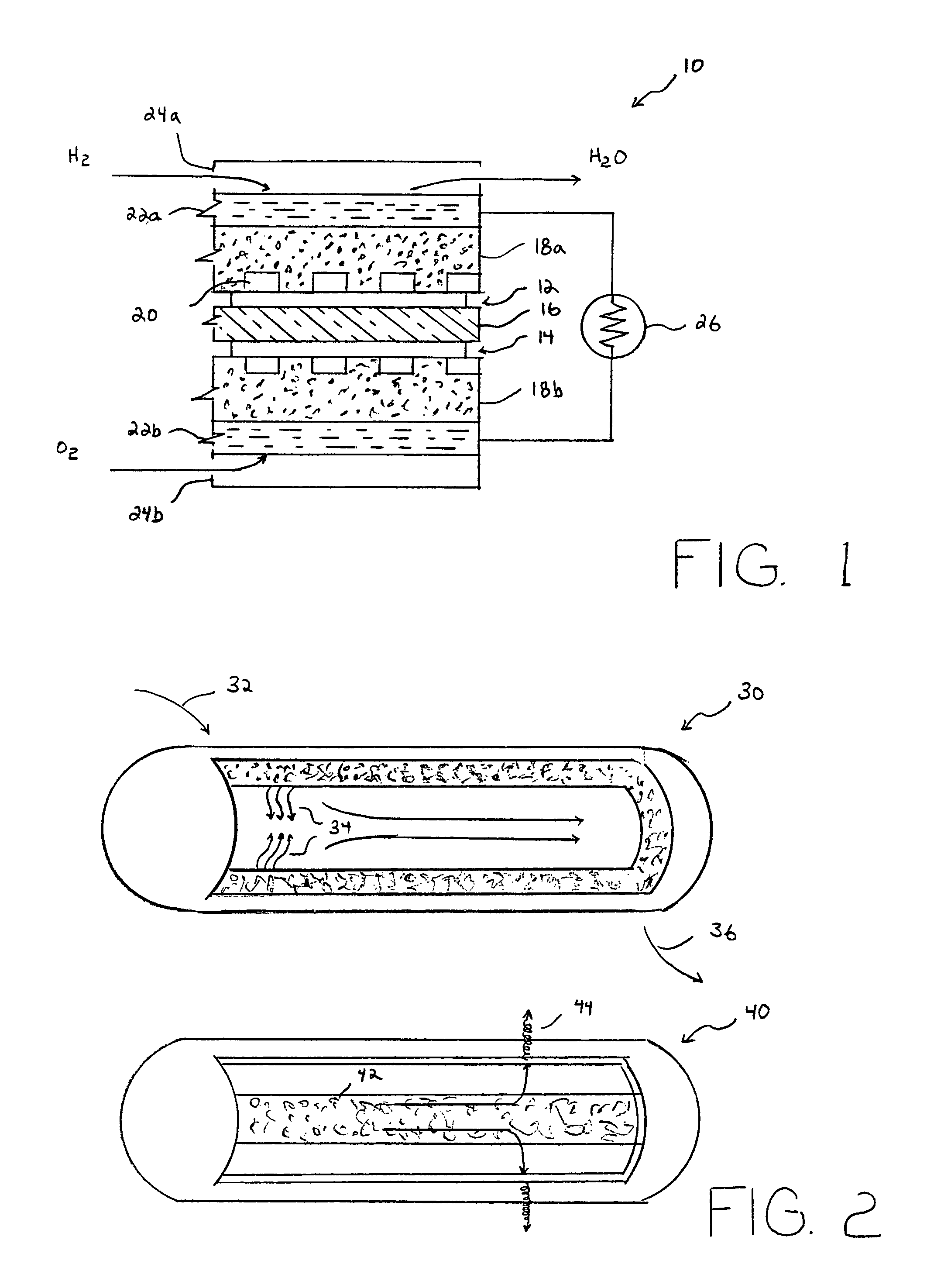
[0023]Turning now to the drawings, FIG. 1 illustrates one form of a fuel cell 10. It is understood that there are numerous forms of fuel cells with different layouts, different structures, and different numbers and sizes of layers, depending on the fuel cell application. Regardless of the differences in fuel cell types, applications, layouts, and structures, it is contemplated that any electrochemical device that converts chemical energy of a reaction to an electrical energy is henceforth referred to as a fuel cell. The example shown in FIG. 1 is that of only one type of fuel cell having a plurality of layers, including a fuel electrode (anode) 12 to which fuel is fed. It is understood, however, that the term “fuel cell” used herein contemplates all types of fuel cell configurations, layouts, structures and electrochemical reactions necessary to generate electrical energy from chemical energy.

[0024]An oxidant electrode (cathode) 14 allows oxygen-containing gas to be fed. An ion exch...


PUM


Abstract

A thermal transfer system, a heat sink, and a method for transferring heat are provided. The thermal transfer system includes a fuel cell that can produce a fluid. A wick is provided to transfer the fluid to a destination at which a heat source is present. An enclosure having a porous fluid-permeable external wall can surround the fluid at the destination. When the fluid permeates or condenses on the external wall exterior surface, air exposure of that external wall will cause evaporative cooling of the fluid, and thereby enhance the cooling effect at the heat source. The fluid is a natural byproduct of the fuel cell. Accordingly, the thermal transfer system not only cools a heat source, but produces electric current. The heat sink can be thermally coupled to the heat source, and can have a plurality of fins extending from a base. One or more fins can have a fluid-permeable external wall for evaporative cooling. Fluid can be transferred more efficiently using a wick placed somewhere within the internal radial dimension of a pipe that extends from the fuel cell to the heat source. The external wall of the pipe can also be porous to maximize the fluid entrapment on the inner surface and the evaporative cooling on the external surface.

Description

BACKGROUND OF THE INVENTION[0001]1. Field of the Invention[0002]The present invention relates in general to the field of fuel cells and thermal exchange devices, alternatively known as heat sinks and, more particularly, to a fluid-permeable heat sink that is integrated with a byproduct of the fuel cell to cool a component or components thermally coupled to the heat sink.[0003]2. Description of the Related Art[0004]The following descriptions and examples are not admitted to be prior art by virtue of their inclusion within this section.[0005]It is generally known that fuel cell technology provides a source of electric power. Fuel cells are electrochemical devices that convert the chemical energy of a reaction into electrical energy. The basic physical structure or building block of a fuel cell consists of an electrolyte layer in contact with a porous anode and cathode on either side of the electrolyte.[0006]In a typical fuel cell, gaseous fuels are fed continuously to the anode and an...

Claims


Application Information

Patent Timeline
Patent Type & Authority Patents(United States)
IPC IPC(8): F28C1/00
CPCF28D15/0266F28D15/0275F28D15/04F28D21/0015H01L23/427H01M8/04059H01M8/04701F28D2021/0029F28D2021/0043H01L2924/0002Y02E60/50H01L2924/00
Inventor HASKELL, BERT
Owner ZEBRA TECH CORP
Why Eureka
Try Eureka