Liquid shutoff valve gear

a technology of liquid shutoff valve and shutoff valve, which is applied in the direction of functional valve types, transportation and packaging, containers, etc., can solve the problems of small gap produced between seat members, flowed-out fuel cannot be recovered but flows out to the outside of the fuel tank, and the splash of fuel can be blown to the inner side, so as to achieve the effect of preventing the splash of liquid, and simple shap

Inactive Publication Date: 2010-08-10
PIOLAX CO LTD
View PDF10 Cites 23 Cited by
  • Summary
  • Abstract
  • Description
  • Claims
  • Application Information

AI Technical Summary

Benefits of technology

[0010]As an aspect of the invention, there is provided a liquid shutoff valve gear capable of restraining a splash of a liquid and firmly preventing the liquid from flowing out to outside by a simple shape.
[0015]According to the first aspect of the invention, a phenomenon in which the liquid directly enters the exhaust port provided at inside of the upper chamber from the opening portion of the partition plate can firmly be prevented by the partition wall in the cylindrical shape provided at the peripheral edge of the opening portion. Further, even when the liquid assumedly enters inside of the upper chamber from the opening portion of the partition plate, the liquid can swiftly be guided to the opening portion by way of the notched portion at the partition wall.
[0016]Here, when the floor face of the upper chamber is formed in the flat shape or the cone shape for guiding the liquid to the opening portion by way of the notched portion as in the second aspect of the invention, the liquid is made to be easy to move and the liquid can be guided to the opening portion further swiftly.
[0017]Further, when the notched portion is formed at the portion which is not opposed to the opening of the gas introducing port as in the third embodiment of the invention, the partition wall in the cylindrical shape is opposed to the opening of the gas introducing port. Therefore, even when the liquid advances from the gas introducing port, the liquid can be prevented from directly entering the exhaust port firmly by the partition wall.
[0018]Further, according to the fourth embodiment of the invention, for example, when the liquid shutoff valve gear is inclined, the liquid at inside of the upper chamber is stored along the inner peripheral face, and therefore, the liquid can be restrained from leaking out from the opening of the exhaust port projected from the inner peripheral face.
[0019]As has been explained above, according to the invention, the splash of the liquid can be restrained and the liquid can firmly be prevented from flowing out to outside by the simple shape.

Problems solved by technology

However, even when the splash of the fuel can be prevented in closing the valve by such a constitution, in a case of rocking the fuel tank by vibration or the like, a small gap is produced between the seat member and the connecting paths, and there is a concern of blowing the splash of the fuel to inner sides of the connecting paths.
However, according to the stop valve of JP-A-8-159318, when the splash of the fuel flows out by riding over the fuel splash flow out preventing plate, the flowed-out fuel cannot be recovered but flows out to outside of the fuel tank over time.
However, according to the liquid shutoff valve gear of JP-A-2003-185046, a structure thereof becomes complicated such that it is necessary to provide a shutoff valve for closing the second opening portion other than a float.

Method used


Image

  • Liquid shutoff valve gear
  • Liquid shutoff valve gear
  • Liquid shutoff valve gear

Examples


Embodiment Construction

[0034]An embodiment of the invention will be explained in details in reference to the drawings as follows.

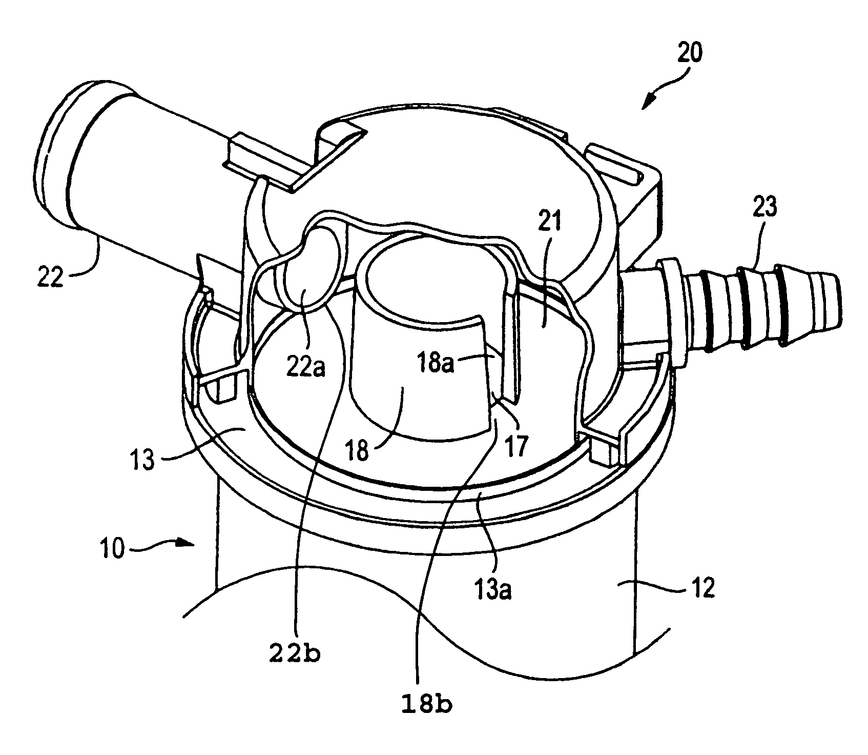
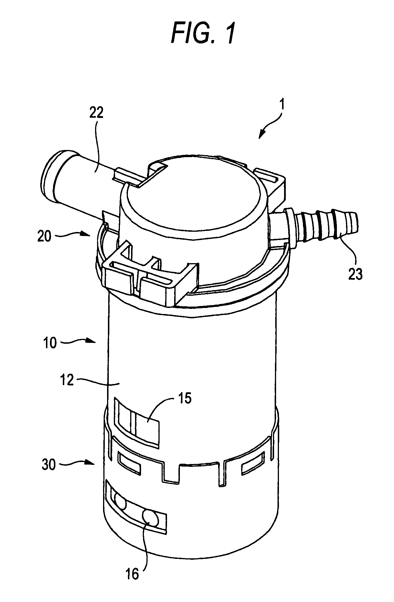
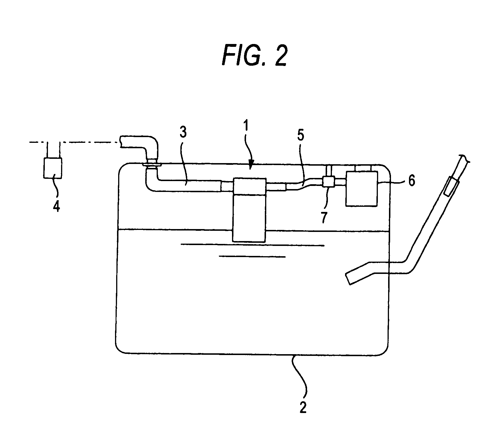
[0035]FIG. 1 through FIG. 13B are views showing a constitution of a liquid control valve gear according to the embodiment of the invention. FIG. 1 is a perspective view showing a total constitution of the liquid shutoff valve gear, and FIG. 2 is a side sectional view showing a state of installing the liquid shutoff valve gear at a fuel tank.

[0036]As shown by FIG. 1, an outer shell of the liquid shutoff valve gear is formed by a housing 1 molded by a resin in a cylindrical shape. As shown by FIG. 2, the liquid shutoff valve gear is provided at an upper space at inside of a fuel tank 2 (hermetically closed vessel) for containing a liquid fuel (hereinafter, simply referred to as fuel) of an automobile or the like and is communicated with a canister 4 at outside thereof by way of a connecting path 3 for exhausting. When a fuel is supplied to inside of the fuel tank 2, a gas of a fue...


PUM


Abstract

A liquid exhaust valve gear includes a housing divided into an upper chamber and a lower chamber by being partitioned by a partition plate having an opening portion, and a float slidably contained at inside of the lower chamber and moved up by receiving liquid inside of the hermetically sealed vessel. An upper end portion of the float is provided with valve means for closing the opening portion of the partition plate in accordance with moving up the float, further, a partition wall in a cylindrical shape is provided to extend in an upper direction from a peripheral edge of the opening portion at inside of the upper chamber, the partition wall is opposed to an opening of an exhaust port, and a notched portion which is not opposed to the opening of the exhaust port.

Description

BACKGROUND[0001]1. Field of the Invention[0002]The present invention relates to a liquid shutoff valve gear installed at an upper portion at inside of a hermetically sealed vessel by providing a function of communicating with outside for exhausting a gas at inside of the vessel in accordance with supply of a liquid.[0003]2. Description of the Related Art[0004]A liquid shutoff valve gear is arranged at, for example, an upper portion of inside of a fuel tank of an automobile or the like and is constituted to communicate with a canister at outside thereof. The liquid shutoff valve gear exhausts an evaporated gas to the canister in accordance with supply of a fuel to inside of the fuel tank. Further, when supply of the fuel reaches a predetermined level, communication with the canister is automatically shut off. Thereby, the liquid shutoff valve gear can detect a fuel amount and prevent the fuel from flowing out. As an apparatus of this kind, there is pointed out a liquid shutoff valve ...

Claims


Application Information

Patent Timeline
Patent Type & Authority Patents(United States)
IPC IPC(8): F16K24/04
CPCF16K24/044B60K15/03519Y10T137/3099Y10T137/0874
Inventor KISHI, MORIHIKO
Owner PIOLAX CO LTD
Why Eureka
Try Eureka