Eureka AIR delivers breakthrough ideas for toughest innovation challenges, trusted by R&D personnel around the world.

Methods and devices for removing material from a body lumen

a technology of body lumens and catheters, applied in the field of atherectomy catheters, can solve the problems of debulking assembly to move outside, and achieve the effect of convenient catheter control and manipulation for users, and convenient atherectomy procedur

Inactive Publication Date: 2010-08-10
TYCO HEALTHCARE GRP LP
View PDF173 Cites 312 Cited by
  • Summary
  • Abstract
  • Description
  • Claims
  • Application Information

AI Technical Summary

Benefits of technology

[0012]The rigid distal portion of the catheter can be rotatably coupled to a flexible portion of a catheter through a connection assembly, such as one or more articulation members, pivot pins, one or more flexible joints, or the like. A longitudinal axis of the distal portion of the catheter body will be angled or offset from a longitudinal axis of the cutter and the rest of the catheter when it is deflected from the proximal portion of the catheter. The deflection of the distal portion of the catheter body to an angled or offset configuration relative to the rest of the catheter body can urge the distal portion against the body lumen so as to bias the debulking assembly against an opposite side of the lumen wall. Because the deflection of the distal portion can increase the profile of the catheter and bias the debulking assembly against the body lumen without the use of a balloon, and because the debulking assembly can be exposed outside of the window beyond a diameter of the distal portion such that the target tissue does not have to invaginate the window, the rigid portion of the catheter and the window can be decreased in size (both longitudinally and radially) so as to allow the catheters to reach the tortuous and smaller diameter body lumens and to reduce the trauma to the body lumen (e.g., barotrauma of balloons) during advancement to the target site. In exemplary embodiments, the distal portion of the catheter includes a rigid housing that has a rigid length of approximately 6 mm to 8 mm.
[0014]Depending on the type of occlusion in the body lumen, certain cutter designs are more effective than other cutter designs. In a specific embodiment, the cutter can include a serrated blade. In other embodiments, the cutter can include a non-serrated blade that has been found to be more effective in removing in-stent restenosis. Optionally, the in-stent restenosis cutter can include a bump along its edge to reduce the cutting edge interaction with the stent.
[0018]In some embodiments, a flexible distal tip can be attached to the rigid distal portion of the catheter. The distal tip may be removably or integrally attached to the distal portion of the catheter. By integrating the tip with the distal portion of the catheter body, the joint between the tip and catheter body is eliminated, thus providing a continuous inner diameter from the housing to the tip which results in improved tissue packing. In some embodiments, the distal tip has a reducing stiffness in the distal direction. The gradual change in stiffness results in the elimination of a rigid joint and the decreasing stiffness of the tip can provide better access to tortuous vessels, while being less traumatic to the vessel wall. In other embodiments, however, the flexible distal tip may have a constant flexibility throughout its length.
[0020]Some embodiments of the catheter include a distal tip that facilitates rapid exchange of a guidewire. The distal tip will typically comprise a distal port and a guidewire lumen that can extend proximally from the distal port to a proximal port that is disposed proximal to the cutter. In one particular embodiment, the proximal port is disposed approximately 30 cm from the distal port.
[0022]In exemplary embodiments, the methods of the present invention use a cutter to debulk the body lumen. In such embodiments, the cutter is rotated and the cutter is exposed through a cutting window and biased into contact with the material in the body lumen. By coupling the severing and biasing steps, it is easier for the user to control and manipulate the catheter, thus making it easier to perform the atherectomy procedure.

Problems solved by technology

For example, movement of the debulking assembly from a distal position to a proximal position can cause the distal portion to deflect and cause the debulking assembly to move outside of the window, beyond an outer diameter of the catheter body.

Method used


Image

  • Methods and devices for removing material from a body lumen
  • Methods and devices for removing material from a body lumen
  • Methods and devices for removing material from a body lumen

Examples


Embodiment Construction

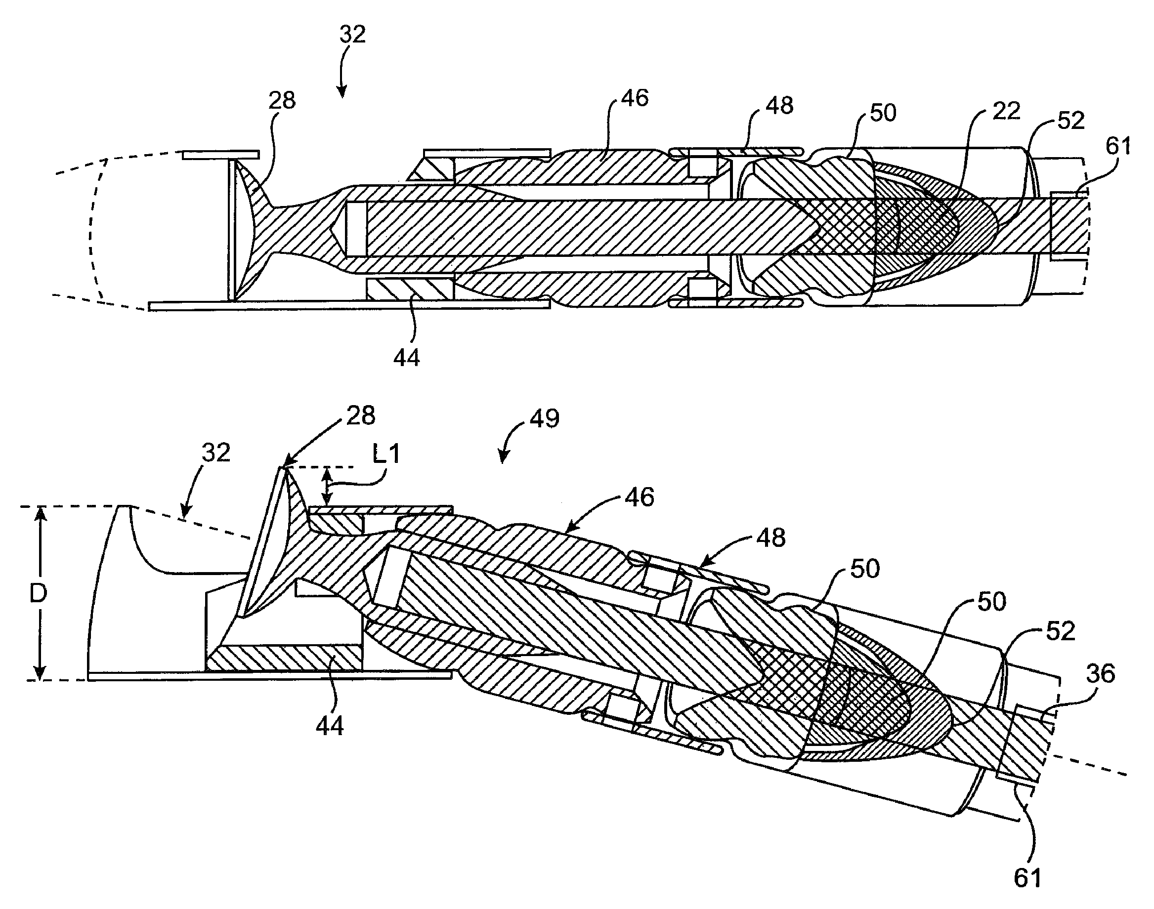
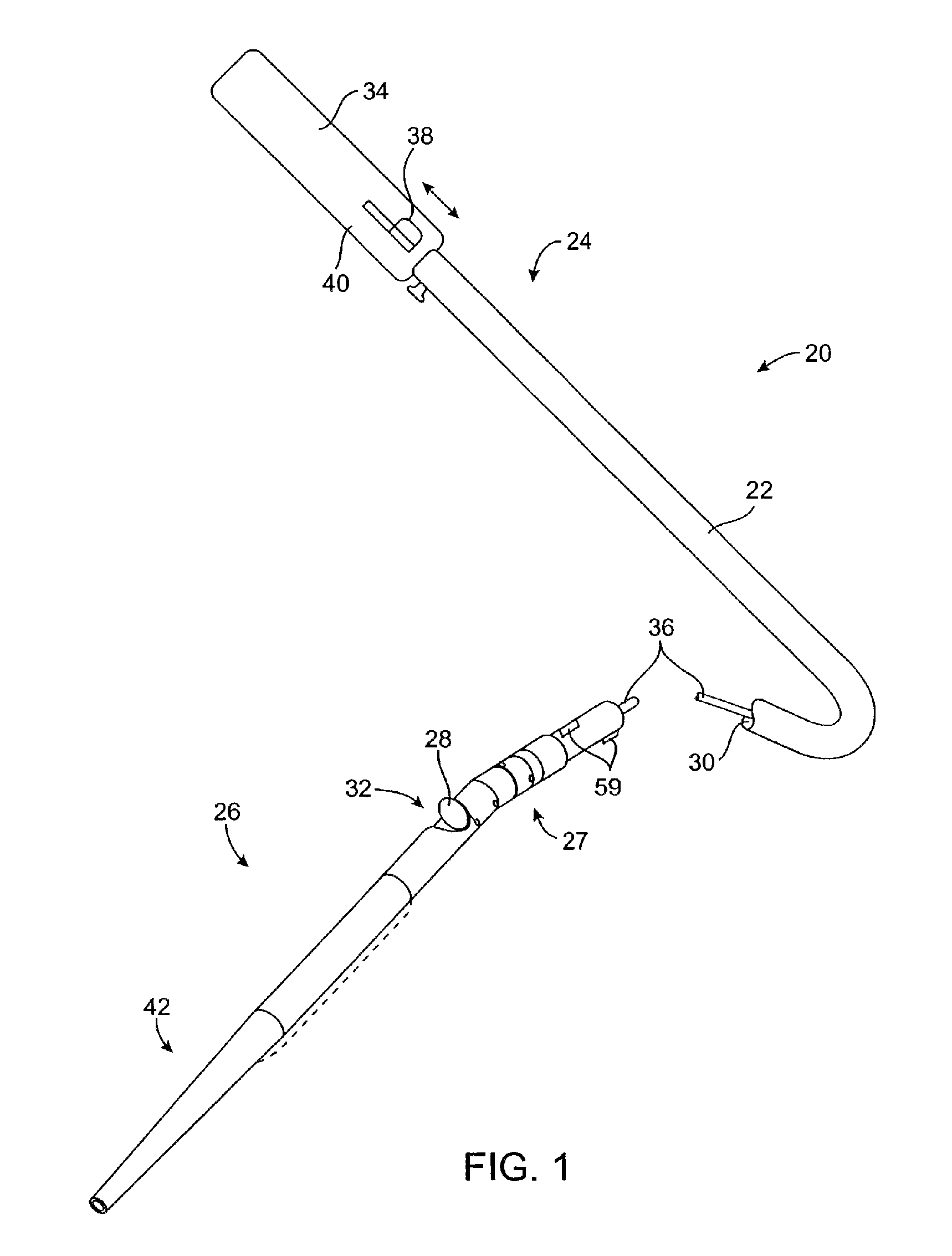
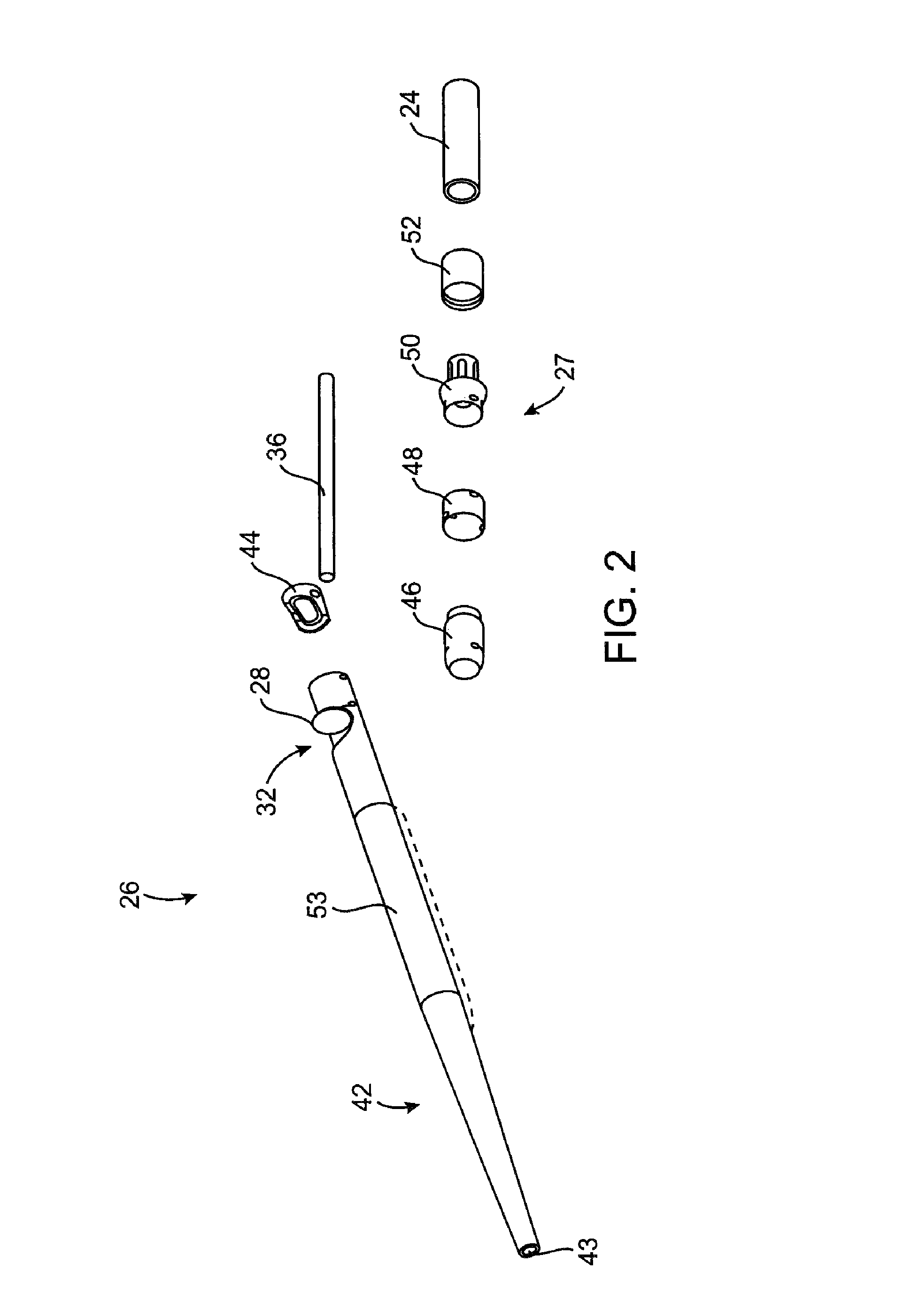
[0051]The methods and systems of the present invention are designed to debulk atheroma and other occlusive material from diseased body lumens, and in particular coronary arteries, de novo lesions, and in-stent restenosis lesions. The systems, devices and methods, however, are also suitable for treating stenoses of the body lumens and other hyperplastic and neoplastic conditions in other body lumens, such as the ureter, the biliary duct, respiratory passages, the pancreatic duct, the lymphatic duct, and the like. Neoplastic cell growth will often occur as a result of a tumor surrounding and intruding into a body lumen. Debulking of such material can thus be beneficial to maintain patency of the body lumen. While the remaining discussion is directed at debulking and passing through atheromatous or thrombotic occlusive material in a coronary artery, it will be appreciated that the systems and methods of the present invention can be used to remove and / or pass through a variety of occlus...


PUM


Abstract

A debulking catheter comprising a debulking assembly for debulking a body lumen. The catheters of the present invention can include a flexible proximal portion coupled to a rigid distal portion. A tissue debulking assembly can be disposed within the rigid portion to debulk the body lumen. In exemplary embodiments, the rigid portion is rotatably coupled to the flexible portion such that rotation or deflection of the rigid portion, relative to the flexible portion, can expose the tissue debulking assembly through a window in the catheter to debulk the body lumen.

Description

CROSS-REFERENCES TO RELATED APPLICATIONS[0001]The present invention claims benefit of Provisional Patent Application Ser. No. 60 / 257,704, filed Dec. 20, 2000, entitled “Debulking Catheter” and Provisional Patent Application Ser. No. 60 / 272,273 filed Feb. 27, 2001, the complete disclosures of which are incorporated herein by reference.[0002]The present invention is also related to U.S. patent application Ser. No. 09 / 377,884, filed Aug. 19, 1999, now U.S. Pat. No. 6,638,233, entitled “Apparatus and Methods for Material Capture and Removal” and Ser. No. 09 / 377,894, filed Aug. 19, 1999, now U.S. Pat. No. 6,447,525, entitled “Apparatus and Methods for Removing Material From a Body Lumen,” the complete disclosures of which are incorporated by reference.BACKGROUND OF THE INVENTION[0003]The present invention relates generally to systems and methods for debulking body lumens. More particularly, the present invention relates to atherectomy catheters for excising atheroma and other materials f...

Claims


Application Information

Patent Timeline
Patent Type & Authority Patents(United States)
IPC IPC(8): A61B17/22A61B17/00A61B17/28A61B17/32A61B18/14
CPCA61B17/320758A61B17/320783A61B8/12A61B17/2202A61B17/320725A61B2017/00685A61B2017/2927A61B2017/320032A61B2017/320791A61B2017/320775
Inventor PATEL, HIMANSHUSIMPSON, JOHN B.DOUD, DARREN G.
Owner TYCO HEALTHCARE GRP LP
Why Eureka
Eureka Blog
Learn More