Calibrated quadrature very low intermediate frequency receiver

a receiver and intermediate frequency technology, applied in the field of radio frequency receiver circuits, can solve the problems of narrow channel bandwidth and the rejection of image frequencies by vlif receivers, and achieve the effects of minimizing calibration times, simplifying calibration measurements, and optimizing vlif image rejection

Active Publication Date: 2010-08-10
QORVO US INC
View PDF6 Cites 63 Cited by
  • Summary
  • Abstract
  • Description
  • Claims
  • Application Information

AI Technical Summary

Benefits of technology

[0008]The present invention is a quadrature VLIF receiver, including calibration circuitry, and methods to closely match signal processing of an in-phase signal path and a quadrature-phase signal path to optimize VLIF image rejection. The calibration circuitry includes a variable gain variable-phase calibration signal generator, a variable gain amplifier for each signal path, phase adjustment circuitry for each signal path, and switching circuitry to support calibration steps. The calibration signal generator supplies a calibration signal at the same frequency...

Problems solved by technology

With the growth of the wireless communications industry, wireless communications protocols become more sophisticate...

Method used


Image

  • Calibrated quadrature very low intermediate frequency receiver
  • Calibrated quadrature very low intermediate frequency receiver
  • Calibrated quadrature very low intermediate frequency receiver

Examples


first embodiment

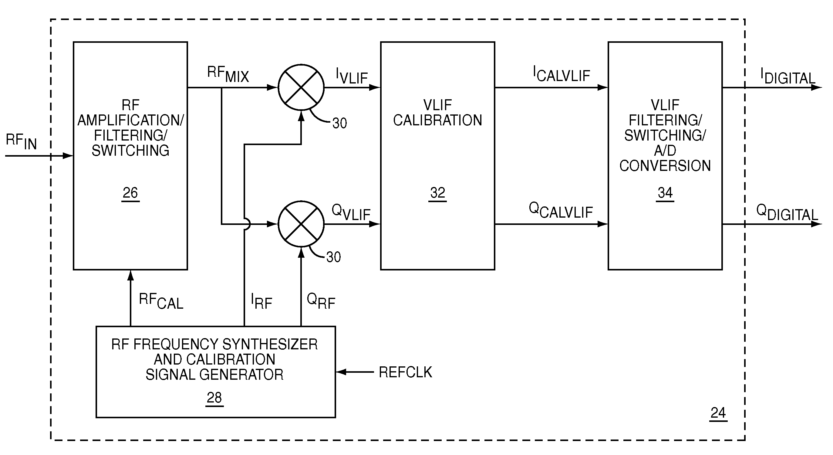
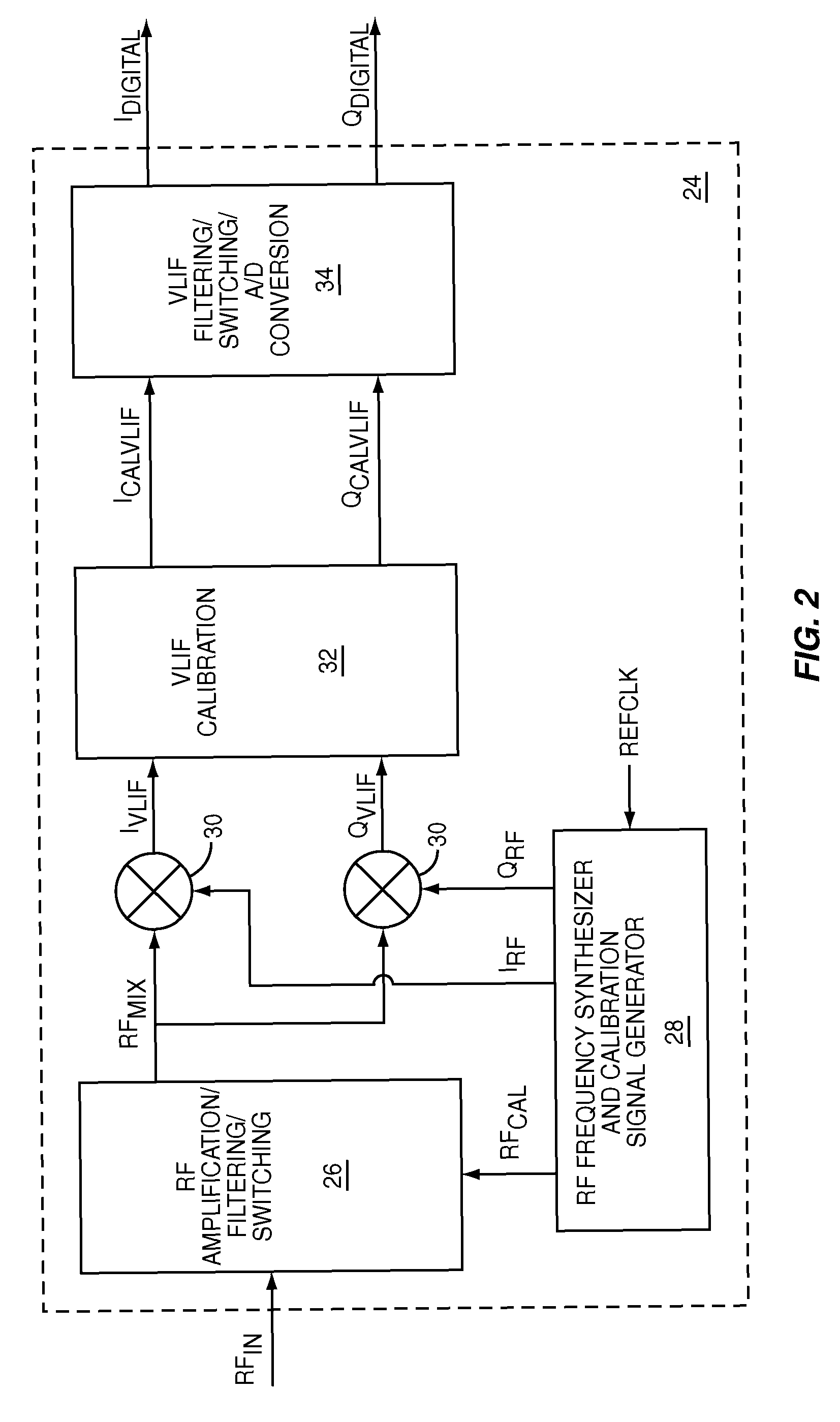
[0033]In the present invention, the RF amplification, filtering, and switching circuitry 26 is designed for a single communications band, as shown in FIG. 3. An LNA 36 receives RFIN and feeds an RF bandpass filter 38, which then feeds an RF mixer preamplifier 40. A first RF switch 42 receives the output from the RF mixer preamplifier 40 and also receives RFCAL, and then selects one of the two to provide a signal to a calibrated RF bandpass filter 44, which then provides RFMIX. During calibration, the first RF switch 42 selects RFCAL. During normal operation, the first RF switch 42 selects the output from the RF mixer preamplifier.

second embodiment

[0034]In the present invention, the RF amplification, filtering, and switching circuitry 26 is designed for four communications bands, as shown in FIG. 4, which may include the PCS band, the DCS band, the GSM band, and the EGSM band. A PCS band LNA 46 and a DCS band LNA 48 receive RFIN and feed a highband RF bandpass filter 50, which then feeds a highband RF mixer preamplifier 52. A second RF switch 54 receives the output from the highband RF mixer preamplifier 52 and feeds a calibrated highband RF bandpass filter 56. An EGSM band LNA 58 and a GSM band LNA 60 receive RFIN and feed a lowband RF bandpass filter 62, which then feeds a lowband RF mixer preamplifier 64. A third RF switch 66 receives the output from the lowband RF mixer preamplifier 64 and feeds a calibrated lowband RF bandpass filter 68. The calibrated highband RF bandpass filter 56 and the calibrated lowband RF bandpass filter 68 feed a fourth RF switch 70, which provides RFMIX. A fifth RF switch 72 receives RFCAL and f...


PUM


Abstract

The present invention is a quadrature VLIF receiver, including calibration circuitry, and methods to closely match signal processing of an in-phase signal path and a quadrature-phase signal path to optimize VLIF image rejection. The calibration circuitry includes a variable gain variable-phase calibration signal generator, a variable gain amplifier for each signal path, phase adjustment circuitry for each signal path, and switching circuitry to support calibration steps. The calibration signal generator supplies a calibration signal at the same frequency as mixer local oscillator signals; therefore, during calibration, all signals downstream of the VLIF mixer are at DC, which simplifies calibration measurements, thereby minimizing calibration times.

Description

FIELD OF THE INVENTION[0001]The present invention relates to radio frequency (RF) receiver circuits, which are used in wireless communications systems.BACKGROUND OF THE INVENTION[0002]With the growth of the wireless communications industry, wireless communications protocols become more sophisticated, often resulting in narrow channel bandwidths. As such, RF receivers must be capable of receiving RF signals on narrow channels with low noise and a high degree of selectivity. Wireless communications systems are often battery powered and must function with minimal power consumption.[0003]A traditional RF receiver architecture is the heterodyne architecture in which a received RF signal is mixed with a local oscillator signal to obtain a lower intermediate frequency (IF) signal. The IF signal is then filtered to the desired channel bandwidth to remove interfering signals and signals from adjacent channels. As channel bandwidths become narrower, the inclination is to reduce the frequency ...

Claims


Application Information

Patent Timeline
IPC IPC(8): H04B17/00H04B1/10
CPCH03D1/2245H04B1/30
Inventor VAN BRUNT, ROGER W.MOFFAT, MARK ALEXANDER JOHNPICKEN, STEVE
Owner QORVO US INC
Why Eureka
Try Eureka