System and method for high-speed insertion of envelopes

a high-speed, envelope technology, applied in envelope openers, packaging goods types, transportation and packaging, etc., can solve the problems of large low efficiency of swing-arm inserters, and low efficiency of automatic inserters, so as to reduce the number of operative device components, reduce the number of adjustments needed, and be readily accessible.

Inactive Publication Date: 2010-08-17
CROWLEY H W
View PDF26 Cites 6 Cited by
  • Summary
  • Abstract
  • Description
  • Claims
  • Application Information

AI Technical Summary

Benefits of technology

[0010]This invention overcomes the disadvantages of the prior art by providing a system and method for inserting contents into envelopes that generally reduces the number of operative device components, locates all components in a readily and accessible location, reduces the number of adjustments needed to change envelope size and contents size, provides an efficient and aesthetically pleasing design, allows for a highly flexible arrangement of backup hoppers to primary hoppers for feeding envelope contents and otherwise affords a substantial number of improvements over currently available envelope inserters.
[0011]According to an illustrative embodiment, the device includes a “low-slung” swing arm design with a plurality of grippers for retrieving contents from hoppers and depositing contents on a moving raceway. The low-slung design employs a moving beam and a pair of opposing arms that are secured in a pivoting relation to a pair of respective uprights. This includes closely fitted shims so as to maintain a high degree of parallelism within the structure. This low-slung design insures that the area above the arm is relatively free of any inconvenient components that interfere, obstruct or hinder an operator's loading of the hoppers, or obscure his or her view of the hoppers' contents. The contents hoppers include back and side supports that are easily adjustable and / or removable, and the entire working surface or table top, when removing the envelope hopper as well, can be pivoted into an inverted position with the swing arm extending into the volume of the underlying device housing. In this pivoted-open position, the moving / operative components of the device are fully exposed to the user at waist level for extremely easy inspection and servicing.
[0012]In an illustrative embodiment, device components are powered by a central drive motor that is attached to the underside of the feed table. Three shafts power all the components. One of the shafts is a continuously rotating shaft that powers elements requiring continuous motion. An interconnected shaft includes an indexer to provide intermittent motion to power, for example, the contents raceway belt. A third shaft arranged on an axis perpendicular to the first two shafts (fixed and intermittent) powers the swing arm and envelope inserter components. All shafts and their respective power take-offs are mounted on the underside of the table and readily accessible.
[0013]In an embodiment of the invention, the front face of the housing includes a concave panel that is aesthetically pleasing and also provides additional clearance for an operator's knees, etc. A further embodiment of this invention provides other desirable features such as moveable feet that allow the height of the housing to be raised and lowered to suit an operator. These feet can be electrically (or otherwise) powered in an embodiment of the invention. In addition, the device includes an elevated control panel with a highly intuitive control-switch-and-status-light display. The control switches include particular controls for activating / deactivating each of the contents hoppers and allowing adjustment contents hoppers to be designated as backups to a given primary hopper. In this manner, the device can be run continuously as each hopper is emptied in turn. The novel raceway belt having timing belt teeth driven by drive and follower sprockets, transports contents downstream to the insertion area and includes spaced-apart lugs that grasp trailing edges of contents and carry them forward, in the downstream direction. These lugs are attached through the belt with through-fasteners and respective backing plates that substitute for one of the timing belt teeth. The backing plates have a slightly smaller dimension than the timing belt teeth so as to avoid damage to drive sprockets.
[0014]In a further embodiment, the swing arm includes easily accessible internal fasteners that allow for quick removal and / or reconfiguration of individual contents grippers. Each of the contents grippers are driven by a common camshaft that operates to opening and close the grippers at opposing ends of the swing arm arc. Each opposing end of the swing arm arc, respectably, picks up contents from a hopper and deposits the contents onto the raceway. In a further embodiment, the insertion area of the device can include a not-moving table section that avoids many of the needed readjustments common to currently available envelope inserters. This non-moving table section allows for easy adjustment of the device to accommodate different-width envelopes. It relies upon a movable envelope leading edge (downstream) hopper guide plate and a clamp bar having a nip that can be adjusted in an upstream-to-downstream direction so that envelopes enter the constant-cycle envelope drive belt at an appropriate time to ensure proper registration with a downstream contents transfer and stuffing station.

Problems solved by technology

Automatic inserters are large, complex devices that are loaded with contents to be inserted (e.g., individual letter sheets and / or fillers) and envelopes in which these contents are to be inserted.
However, once the various hopper materials are inserted into the envelopes, the net production is significantly slower.
Due to paper handling problems, swing-arm inserters often net less than one third of their capabilities.
After careful study, it is now recognized that there are several issues of unreliability in the feeding of materials in conventional inserter devices.
Many device areas are subject to jams.
A number of inefficiencies and disadvantages have been noted in prior art swing arm inserters, for example, the overlying swing-arm structure of the inserter is complicated and difficult to access owing to a large number of interconnecting shafts that drive the various arm and gripper components.
These shafts require a complicated series of adjustments and tuning to insure proper function.
They also obscure access to, and view of, the contents feed hoppers, and more generally interfere with the operator's loading, unloading and operation of the device.
Repair and service of the mechanism is therefore inconvenient and requires the service person to stoop and crawl beneath the device for even the most basic tasks.
Other aspects of prior art inserters are similarly deficient.
Likewise, the inserter is constructed with a housing and table that are placed at an average height for an average worker with no easy way to change that height to accommodate shorter or taller operators.
Also, while prior art inserters may contain a facility for dealing with the exhaustion or jamming of a “primary” contents hopper by providing a backup, or secondary contents hopper, such backup implementations are non-intuitive and difficult for an operator to implement.
Moreover, prior art inserters generally lack straightforward design in their individual components and power-transmission, making them more expensive to manufacture, more difficult to repair, and more prone to misfeed, due to bad tuning (given the many interconnected parts, which must interact perfectly).

Method used


Image

  • System and method for high-speed insertion of envelopes
  • System and method for high-speed insertion of envelopes
  • System and method for high-speed insertion of envelopes

Examples


Embodiment Construction

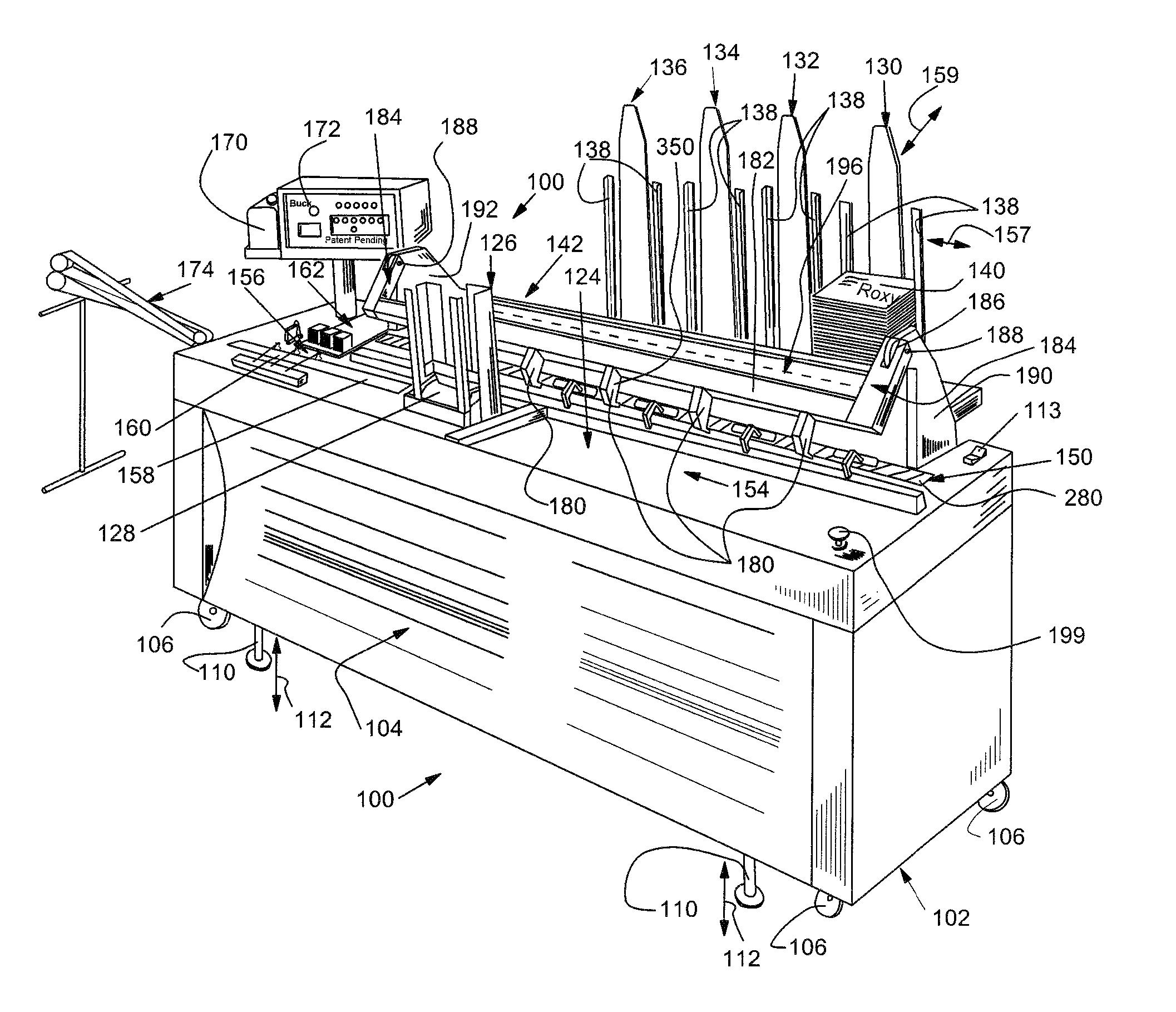
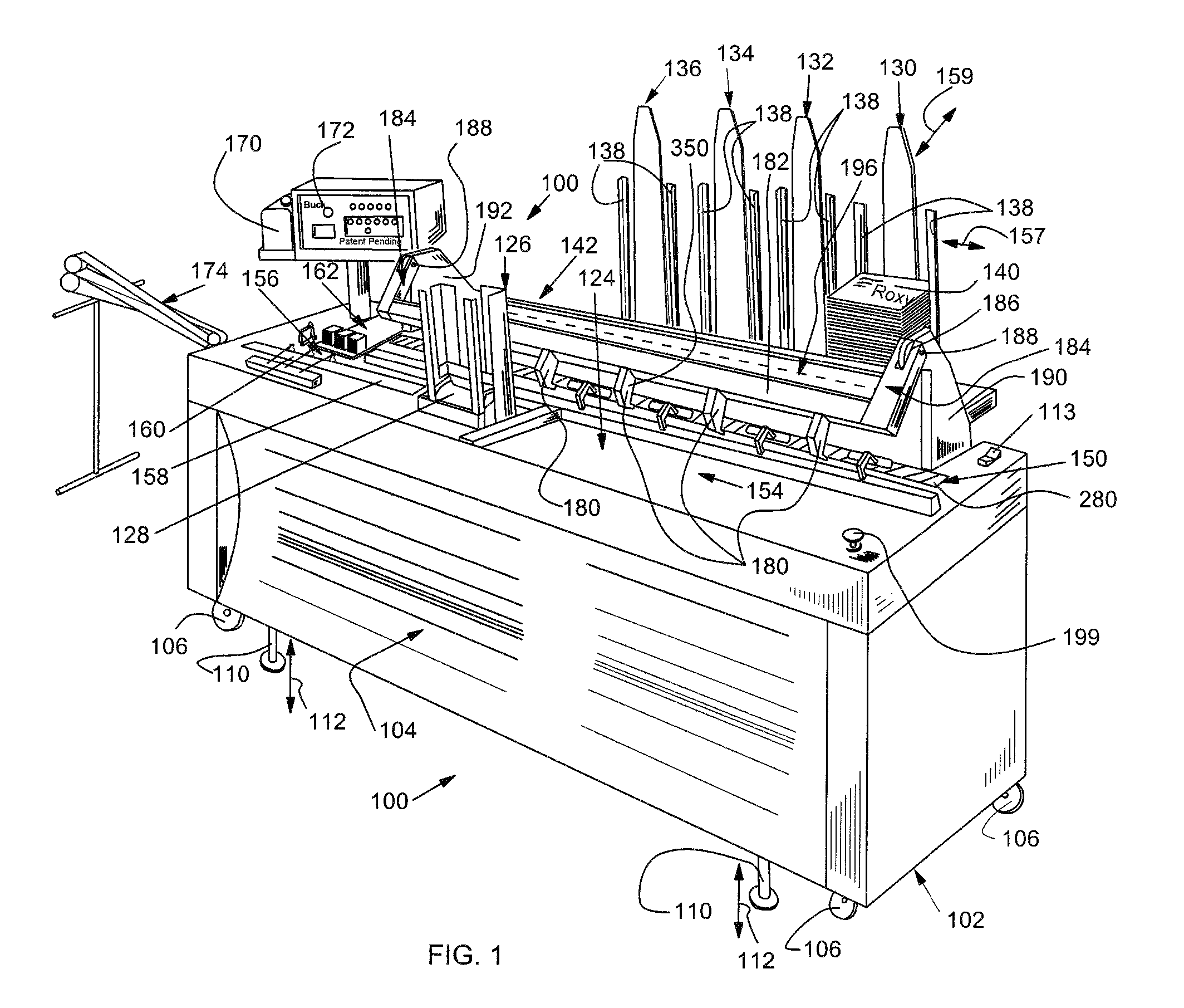
[0030]A system for inserting contents into envelopes 100 is shown in FIG. 1. In overview, the system 100 (also termed herein generally as the “inserter” or “device”) includes a main housing 102 having a concave front panel 104 that particularly aids workers in gaining closer access to the device (with room for knees), and also provides a unique, pleasing appearance to the device housing 102.

[0031]The housing 102 is supported on at least four heavy duty caster wheels 106 that provide portability. In general the housing 102 is a relatively lightweight structure consisting of an internal framework (not shown) and removable covering panels that allow access to the device's interior (as an alternative to the flipping-table system described below). The caster wheels 106 are supplemented by at least four (located adjacent each of the four caster wheels) retractable feet 110 that resist sliding, once deployed. The feet move up and down (double arrows 112) based upon a manual or automated dr...


PUM


Abstract

This invention overcomes the disadvantages of the prior art by providing a system and method for inserting contents into envelopes that generally reduces the number of operative device components, locates all components in a readily and accessible location, reduces the number of adjustments needed to change envelope size and contents size, provides an efficient and aesthetically pleasing design, allows for a highly flexible arrangement of backup hoppers to primary hoppers for feeding envelope contents and otherwise affords a substantial number of improvements over currently available envelope inserters. The illustrative embodiment includes a feed table with a low-slung swing arm for handling contents, a pivoting feed table that exposes the operative components on the underside, a novel raceway belt with projecting lugs for transporting contents to the insertion area, a primary and secondary contents hopper backup system, a mechanism for easily adjusting for different-sized envelopes, and a variety of other novel features.

Description

RELATED APPLICATION[0001]This application claims the benefit of U.S. Provisional Application Ser. No. 60 / 969,912 entitled SYSTEM AND METHOD FOR HIGH-SPEED INSERTION OF ENVELOPES, by H. W. Crowley, filed Sep. 4, 2007, the teachings of which are expressly incorporated herein by reference.FIELD OF THE INVENTION[0002]This invention relates to high-speed envelope inserters used for high-volume mailing operations.BACKGROUND OF THE INVENTION[0003]Current estimates place the number of envelopes used annually in the United States at over 100 billion. A significant percentage of these envelopes are used in connection with bulk mailings, and are accordingly filled, addressed and processed by a variety of automated devices. A lynchpin of all automated processes is the automatic envelope inserter. Automatic inserters are large, complex devices that are loaded with contents to be inserted (e.g., individual letter sheets and / or fillers) and envelopes in which these contents are to be inserted. Oth...

Claims


Application Information

Patent Timeline
Patent Type & Authority Patents(United States)
IPC IPC(8): B65B57/14
CPCB43M3/045B65H3/38B65H3/44B65H39/043B65H39/055B65H2402/441B65H2403/512B65H2403/514B65H2404/232B65H2404/242B65H2405/51B65H2405/52B65H2405/5812B65H2511/414B65H2511/524B65H2551/14B65H2601/321B65H2601/324B65H2701/1916B65H2801/66B65H2220/02B65H2220/03B65H2220/01B43M3/04B43M7/004
Inventor CROWLEY, H. W.
Owner CROWLEY H W
Why Eureka
Try Eureka