Modular femoral prosthesis with on-axis junction

a femoral and module technology, applied in the field of total hip arthroplasty, can solve the problems of limiting the applicability and safety of the design for patients, affecting the quality of the difficulty of each assembly and disassembly of the trial neck and the final prosthetic neck assembly, so as to achieve a larger and stronger neck/stem junction, less variation in wall thickness, and easy and less expensive

Active Publication Date: 2010-08-17
MURPHY STEPHEN B
View PDF19 Cites 59 Cited by
  • Summary
  • Abstract
  • Description
  • Claims
  • Application Information

AI Technical Summary

Benefits of technology

[0012]Another object is to provide a femoral prosthesis which is rotationally stable, yet relatively easy and inexpensive to manufacture.
[0013]Yet another object is to provide a prosthesis of this type which is stronger than conventional implants because it is designed to better match the natural shape of the femur into which it is implanted.
[0016]A further object of the invention is to provide a modular hip prosthesis whose design facilitates its implantation during minimally invasive hip arthroplasty.
[0020]In addition, rather then providing a generally cylindrical junction as depicted in FIG. 6, the junction in the present implant is relatively long and has a relatively large non-cylindrical cross-section which more closely matches the natural shape of a femur. Thus, there is less variation in the wall thickness of the stem surrounding the socket in the stem. This allows a larger and stronger neck / stem junction to be provided than would be the case with an implant having a cylindrical junction taper. Moreover, my prosthesis is devoid of anti-rotation devices such as teeth, locking pins and threaded fasteners. Therefore, it is easier and less expensive to make than the prior implants requiring such devices.
[0021]Also as we shall see, aligning that junction to the stem axis allows for various neck designs that will permit controlling leg length, offset and version independently, and also creates more opportunities for valgus, varus and anteversion implant options.
[0022]Finally, in the present prosthesis, since the neck / stem junction is aligned with the stem axis, trial and final necks may be assembled easily to the stem thereby expediting minimally invasive hip arthroplasty.

Problems solved by technology

In addition, even where there is sufficient metal to accommodate the socket 13, this junction has limited strength that therefore significantly limits the allowable length of the neck 18 that can be used, thus limiting the applicability and safety of the design for patients who have an unusually long native femoral neck that is being replaced.
Given that the socket 13 is at an angle relative to the longitudinal axis of the femoral prosthesis, each assembly and disassembly of the trial neck and assembly of the final prosthetic neck are difficult.
6,319,256 requires a tight threaded fastener to maintain the junction and is thus potentially rotationally unstable.
However, these interfitting surfaces are hard to machine, making those implants difficult and expensive to manufacture.
In addition, those patented prostheses typified by FIG. 6, have a further disadvantage that the metaphysis of the femur is not cylindrical in shape.
Therefore, the size and strength of a generally cylindrical junction is limited by the minimum wall thickness which, in turn, limits the size and strength of the modular femoral neck that can be associated with the stem.

Method used


Image

  • Modular femoral prosthesis with on-axis junction
  • Modular femoral prosthesis with on-axis junction
  • Modular femoral prosthesis with on-axis junction

Examples


Embodiment Construction

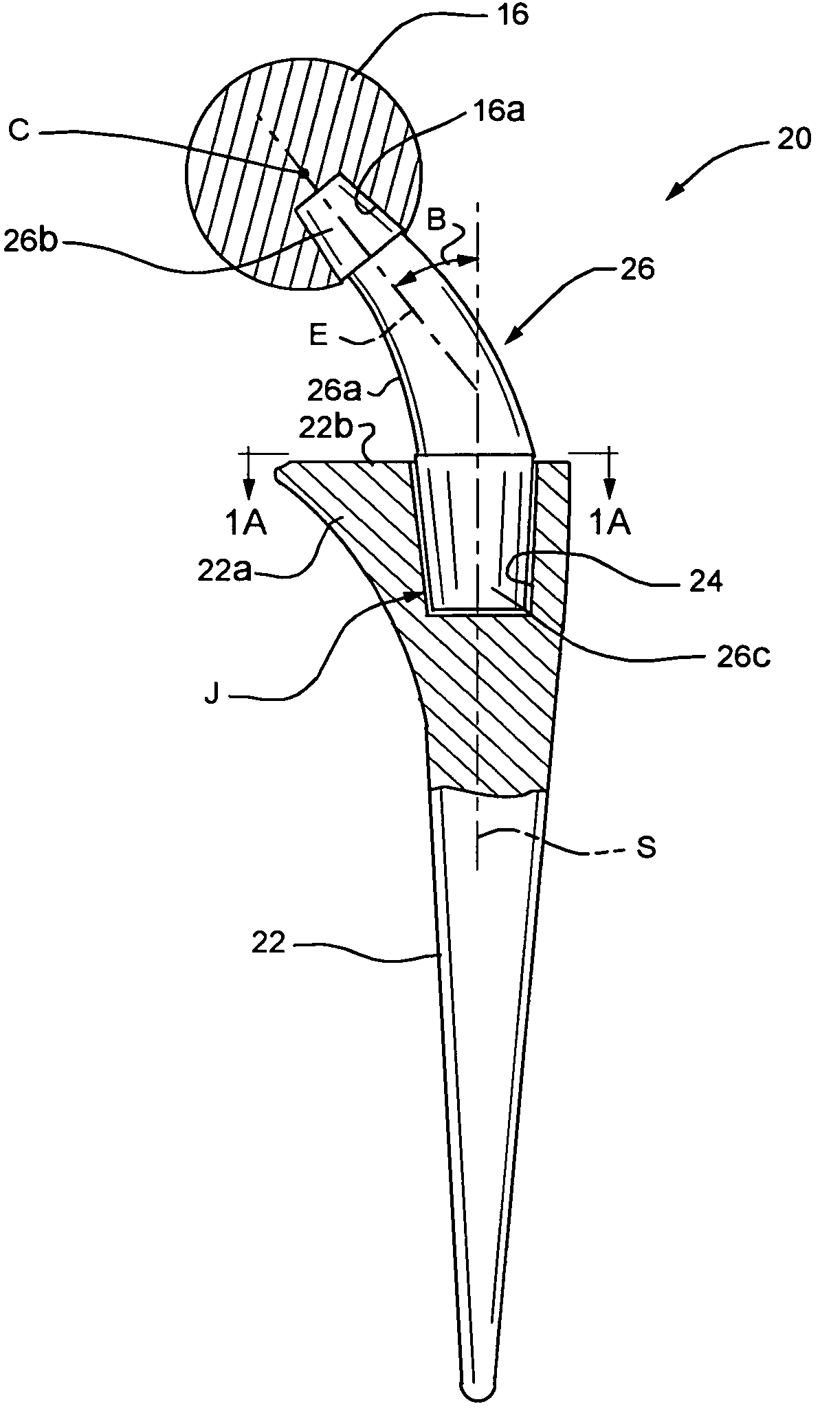
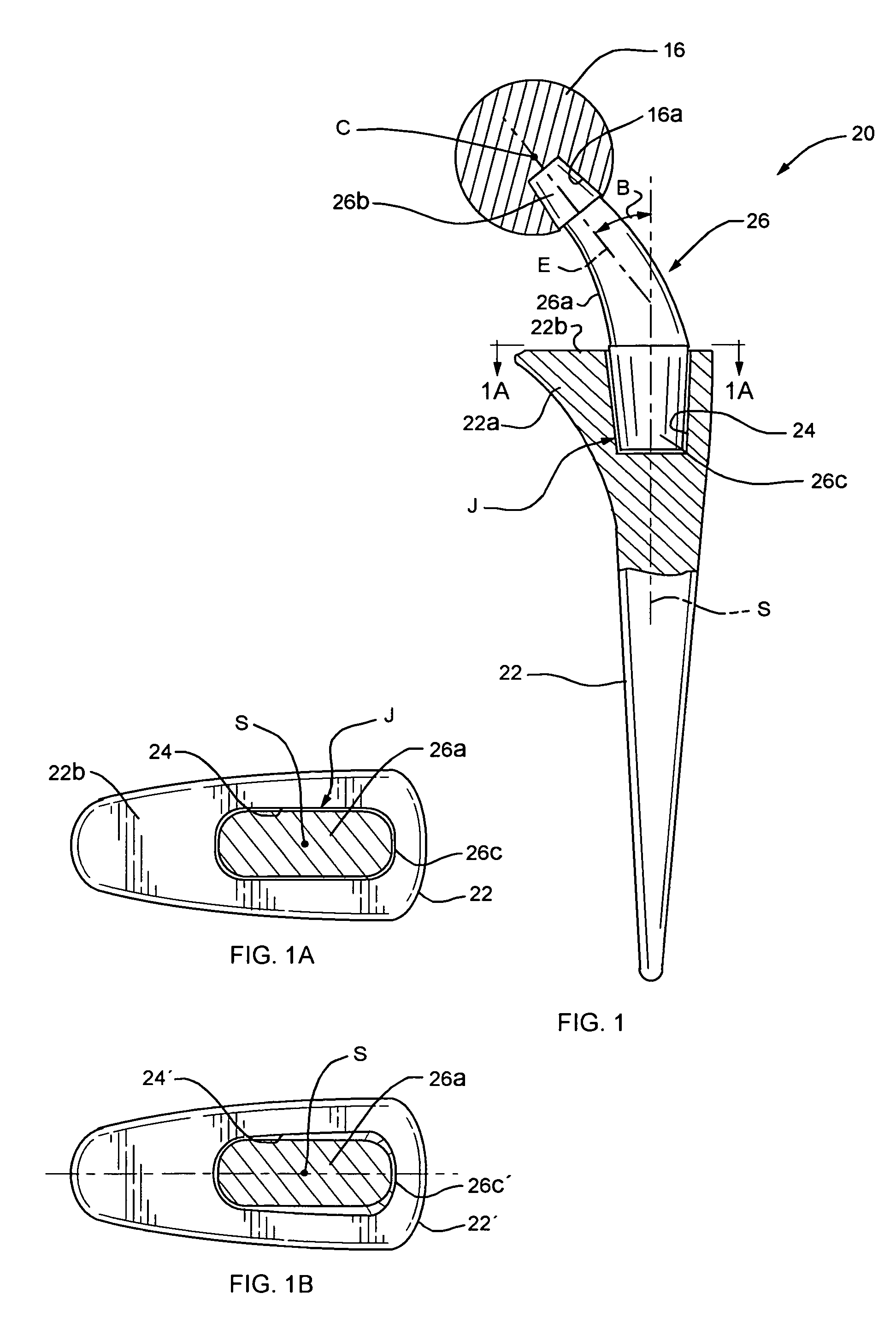
[0032]Refer now to FIG. 1 of the drawings which shows an embodiment of my improved femoral prosthesis. It comprises a stem 22 having a metaphyseal flare 22a leading up to a flat upper surface 22b which is substantially perpendicular to the stem axis S.

[0033]As shown in FIGS. 1 and 1A, a socket 24 extends down into stem 22 from the stem upper surface 22b. Unlike the prior prosthesis depicted in FIG. 5, the socket is centered on the stem axis S and extends in the direction of that axis. Also unlike the prior implant type shown in FIG. 6, the stem socket has a cross-section which is elongated in the direction of the flare 22a. In other words, the socket has sides which extend generally parallel to the sides of stem 22. That being the case, there is more stem material available for the socket 24 in the metaphyseal area 22a of the stem, particularly in the anterior and posterior regions thereof. Accordingly, the socket can be larger and deeper than is the case with the prior prostheses. ...


PUM


Abstract

A modular hip prosthesis includes a femoral stem, a spherical head and a coupling member extending from the head defining a neck whose lower end forms a base which plugs into a socket at the top of the stem to form a tapered neck / stem junction. That junction is aligned with the stem axis and has a cross-section with opposite sides that extend generally parallel to the sides of the stem. With such an arrangement, that junction may be relatively long and have a relatively large cross-sectional area thus making a strong junction even in smaller femoral implants.

Description

[0001]This invention relates to hip replacements. It relates especially to the femoral component of such a replacement.BACKGROUND OF THE INVENTION[0002]1. Field of the Invention[0003]Total Hip Arthroplasty (THA) is an effective surgical procedure for the relief of pain and the restoration of function of a diseased hip. Successful THA has contributed to enhanced mobility and comfortable independent living for people who would otherwise be substantially disabled. As shown in FIG. 5, in total hip replacement surgery, the surgeon may replace a patient's diseased hip joint with a conventional implant consisting of a femoral stem 12 which is inserted into the femur and an acetabular cup 14 which is anchored in the patient's pelvis. The upper end of the stem 12 carries a head or ball-type bearing 16. That head seats in a hemispherical socket 14a defined by the cup 14 so that the stem can swivel relative to the cup about the center of curvature of socket 14a in the manner of a natural hip j...

Claims


Application Information

Patent Timeline
Patent Type & Authority Patents(United States)
IPC IPC(8): A61F2/36
CPCA61F2/3609A61F2/32A61F2/34A61F2/36A61F2/3662A61F2/367A61F2002/30112A61F2002/30158A61F2002/30332A61F2002/30341A61F2002/30355A61F2002/30405A61F2002/30538A61F2002/3055A61F2002/30551A61F2002/30604A61F2002/30616A61F2002/30706A61F2002/3611A61F2002/3625A61F2002/365A61F2002/3652A61F2002/3656A61F2002/4635A61F2220/0025A61F2220/0033A61F2230/0004A61F2230/0026A61F2250/0006A61F2250/0082A61F2310/00023A61F2310/00179A61F2002/30339A61F2002/3054
Inventor MURPHY, STEPHEN B.
Owner MURPHY STEPHEN B
Why Eureka
Try Eureka