Laminated core and method for manufacturing the same

a technology of laminated cores and cores, which is applied in the direction of dynamo-electric machines, electrical equipment, magnetic circuit shapes/forms/construction, etc., can solve the problems of reduced efficiency and vibration in motors, difficult to completely remove gaps, and uneven thickness of laminated cores, so as to prevent the displacement of caulking positions of segment core pieces in the laminating direction, and improve the circular accuracy of multiple segment core pieces

Inactive Publication Date: 2010-08-17
MITSUI HIGH TEC INC
View PDF24 Cites 26 Cited by
  • Summary
  • Abstract
  • Description
  • Claims
  • Application Information

AI Technical Summary

Benefits of technology

[0011]Due to the laminated core according to the present invention, formation of gaps between the laminated core pieces caused by expanded parts of the thickness direction can be prevented. The prevention of the gaps allows the segment core pieces to be closely laminated with each other, thereby resulting in improved magnetic efficiency and high efficiency in the device. Additionally, as the segment core pieces can be closely laminated without gaps, vibrations and noise during operation of the device can be reduced.
[0012]Furthermore, because the circularity and height of the resultant laminated core are made in accordance with its dimensions, the quality control of the laminated core becomes easy and motor quality is improved.
[0013]In the laminated core according to the present invention, the receptacle may be a cutout or a through-hole formed in each segment core piece. Alternatively, the receptacle may be formed by a first hollow and a second hollow respectively provided on a front side and a back side of each segment core piece with central axes of the hollows aligned. In the case of the receptacle formed by the first and second hollows, each of the hollows preferably has a shape of one of a circular cone, a circular truncated cone, a pyramid, a truncated pyramid, a circular cylinder, and a prism. The first hollow and the second hollow in the shape of a circular truncated cone or a four-sided pyramid are particularly advantageous in that formation of the hollows is easy and blades are not worn easily.
[0016]In the laminated core according to the present invention, it is preferable that an engaging part comprising a concave part and a convex part to be engaged with the concave part is formed at the side edges of the adjacent segment core pieces. Thus, the adjacent segment core pieces connected only by the radially-narrow connecting portion are positioned by the engaging part comprising the concave and convex parts, and a radial position and a bending angle of the adjacent segment core pieces are determined. As a result, the circular degree, i.e., the roundness of the bent segment core pieces is improved. As herein used, the concave and convex parts are preferably semicircles or sectors (arc-shaped) having a center angle of 50 degree or more and less than 180 degree, but the shape thereof is not necessarily limited thereto.
[0025]The method for manufacturing the laminated core according to the present invention is capable of further improving the circular accuracy of the multiple segment core pieces by winding and laminating the band of connected segment core pieces.
[0026]Furthermore, the side edges of the adjacent segment core pieces may be closely placed with a slight gap therebetween. In this case, since contacts between the side edges of the segment core pieces are prevented, uneven pitches of the segment core pieces in the circumferential direction can be prevented by adjustment of the gap. For example, displacement of caulking positions of the segment core pieces in the laminating direction can be prevented. Additionally, due to the closely positioned side edges of the adjacent segment core pieces, for example, even if the molding blades for punching the segment core pieces are worn away and burrs are formed, the contacts between the burrs can be prevented. Thus, misalignment of pitches of the segment core pieces in the circumferential direction can be prevented.

Problems solved by technology

The expanded parts create gaps between the laminated segment core pieces, thereby causing uneven thickness of manufactured laminated cores.
However, it is difficult to remove the gaps completely even with the pressure treatments.
Thus, the problems are that reduced efficiency and vibration in the motor using the laminated core are caused, thereby negatively affecting the quality of motors.

Method used


Image

  • Laminated core and method for manufacturing the same
  • Laminated core and method for manufacturing the same
  • Laminated core and method for manufacturing the same

Examples


Embodiment Construction

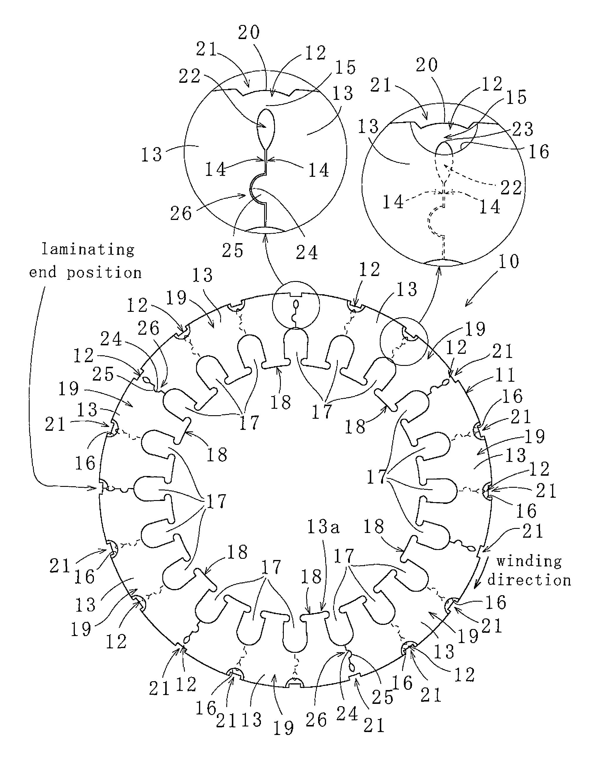
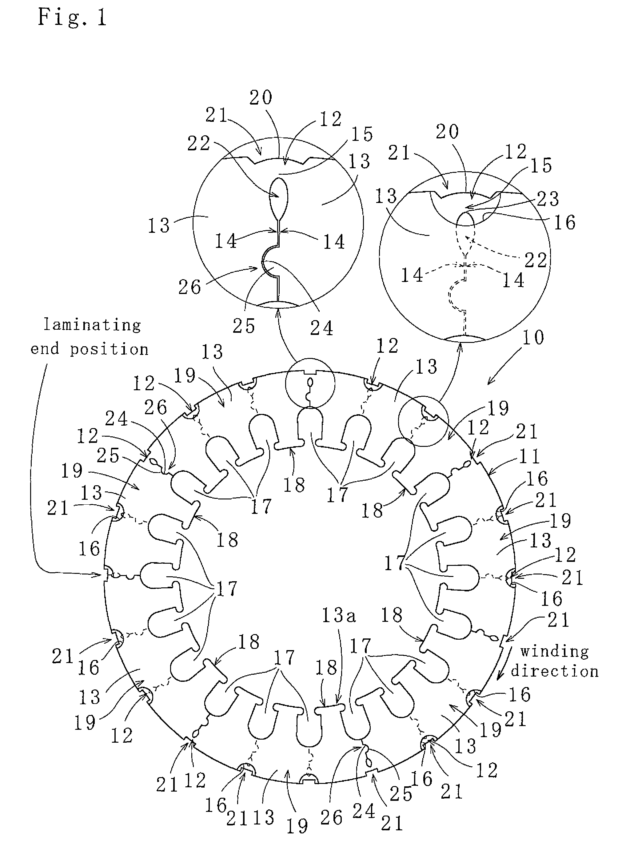
[0032]As illustrated in FIGS. 1-3, a laminated core 10 according to a first embodiment of the present invention is laminated with multiple continuous segment core pieces 13 wound in a spiral form by bending connecting portions 12 of a continuous segment member formed with the adjacent segment core pieces 13 connected by the connecting portions 12 formed on an outer peripheral area 11, with inner circumferential portions 13a (or outer circumferential portions) of the segment core pieces 13 fitted. Accordingly, circumferentially adjacent side edges 14 of the adjacent segment core pieces 13 are either brought into contact with each other or closely placed with a fine gap therebetween. As used herein, to fit the inner circumferential portions 13a (or outer circumferential portions) means to dispose the inner edges (or outer edges) of the segment core pieces 13 on the same circle, or vertically align the inner edges (or outer edges) of the segment core pieces 13. The fitting of the inner...


PUM

PropertyMeasurementUnit
center angleaaaaaaaaaa
timeaaaaaaaaaa

Abstract

A laminated core (10) and a method for manufacturing the same formed with multiple continuous segment core pieces (13) wound in a spiral form by bending connecting portions (12) mutually connecting the segment core pieces (13), the connecting portions (12) being formed in an outer peripheral area (11), while the connecting portions (12) of vertically adjacent layers being displaced in a circumferential direction with inner edges or outer edges of the segment core pieces (13) fitted, the laminated core comprising: a concave cutout (21) provided in a radial exterior of each connecting portion (12) to dispose a radially expanded portion (20) within an outer circle of the laminated core (10), the radially expanded portion (20) being formed with each connecting portion (12) expanding radially outward at the time of bending each connecting portion (12); an interior cutout (22) provided in a radial interior of each connecting portion (12) to define a bending position of each connecting portion (12); and a receptacle (16) provided in a radial exterior of each segment core piece (13) to receive an expanded part (15) formed in the thickness direction at the time of bending each connecting portion (12).

Description

TECHNICAL FIELD[0001]The present invention relates to a laminated core and a method for manufacturing the same, the laminated core being formed by spirally winding multiple continuous segment core pieces connected by connecting portions. The term “laminated core” used herein refers to stators and rotors used for motors and generators.BACKGROUND ART[0002]Conventionally, so-called wound cores have been known for improving yield of core materials used for producing laminated cores. The wound cores are produced by punching not ring-shaped core pieces, but a band of multiple segment core pieces from a magnetic steel strip, and winding and laminating the band of core pieces.[0003]Specifically, as disclosed in, e.g., Japanese published unexamined publication No. 1-264548, Japanese published unexamined publication No. 8-196061, and Published Japanese translation of a PCT international application No. 2004-505595, arc-shaped segment core pieces are punched from a core material using molds, t...

Claims


Application Information

Patent Timeline
Patent Type & Authority Patents(United States)
IPC IPC(8): H02K1/18H02K1/14
CPCH02K15/022H02K15/026Y10T29/49009
Inventor NAGAI, AKIRAMYOJIN, IWAOHOSHINO, AKINORISAKUMA, MASAFUMIYAMAMOTO, HIROYUKISUZUKI, HARUJI
Owner MITSUI HIGH TEC INC
Why Eureka
Try Eureka