
Three stage algorithm for automatic gain control in a receiver system

a receiver system and automatic gain control technology, applied in the field of communication systems, can solve the problems of degrading the receiver performance, affecting the gain-adjusted rf signal, so as to achieve the effect of increasing the gain of the rf amplifier and the gain of the if amplifier

Inactive Publication Date: 2010-08-17
AVAGO TECH WIRELESS IP SINGAPORE PTE
View PDF4 Cites 6 Cited by
  • Summary
  • Abstract
  • Description
  • Claims
  • Application Information

AI Technical Summary

Benefits of technology

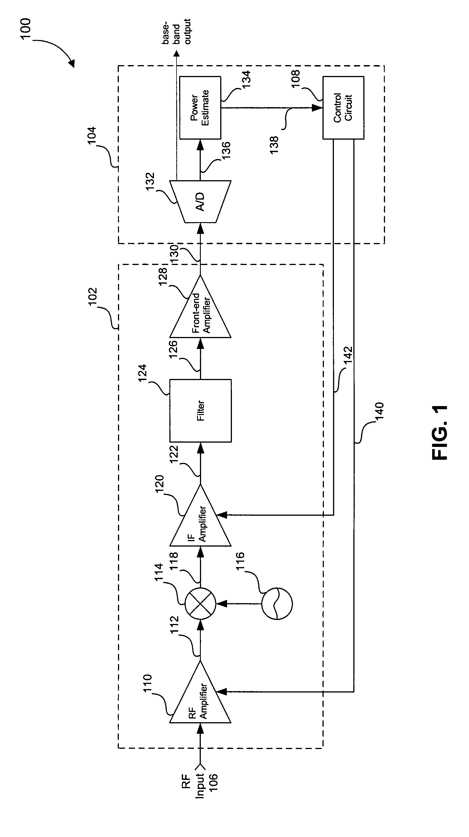
"The patent describes a receiver that can adjust the strength of a radio signal. It uses an RF amplifier and an IF amplifier to amplify the signal. The controller controls the gains of these amplifiers based on the strength of the signal. This results in a higher gain for the IF amplifier when the signal strength is low and a higher gain for the RF amplifier when the signal strength is high. This helps to maintain a good signal quality even when the signal strength fluctuates."

Problems solved by technology

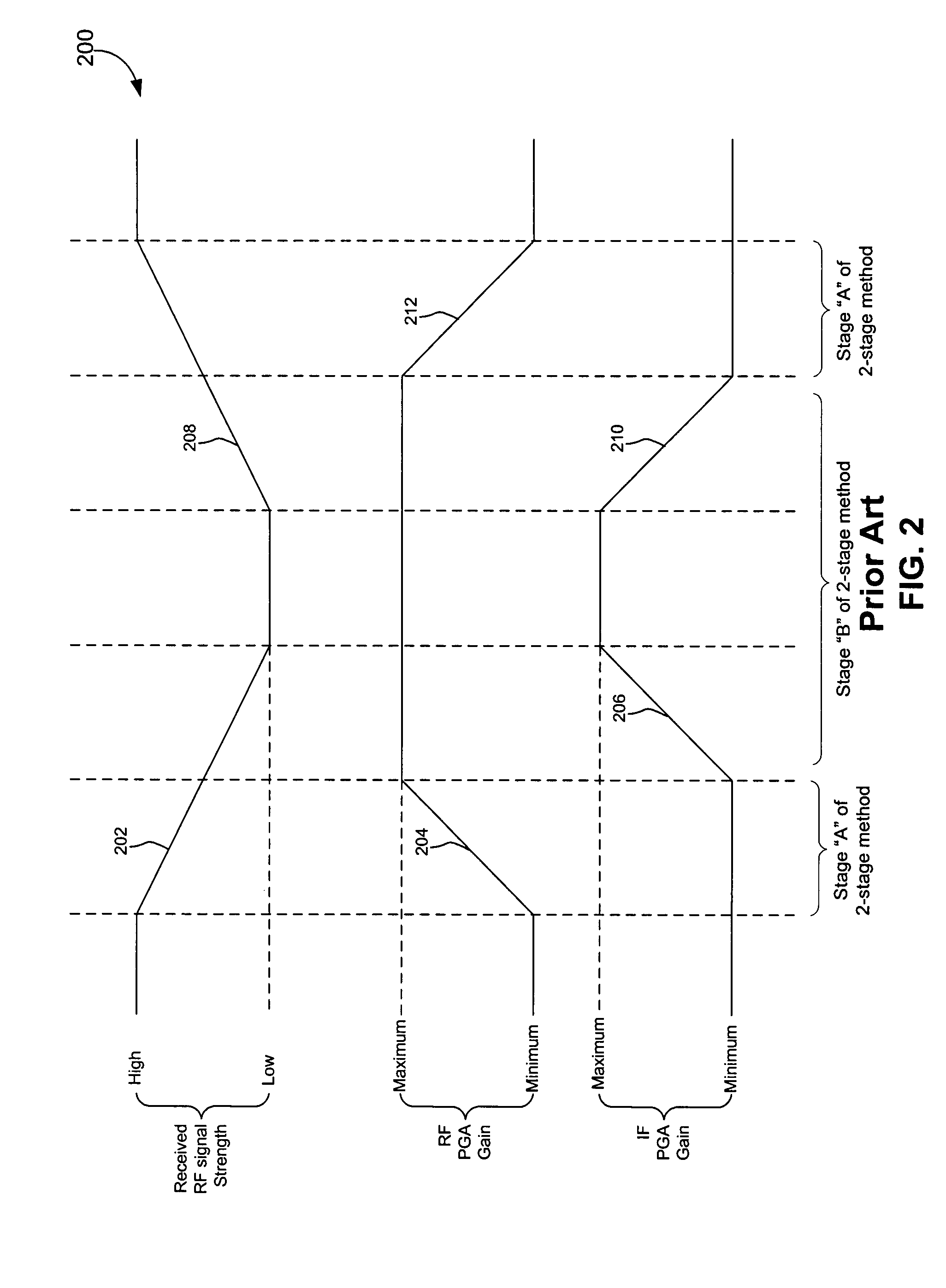
Unfortunately, when received RF signal strength is so high as to require minimal amplification, the conventional AGC circuit causes the RF amplifier to compress the signal that is input to the front-end amplifier.
As a result, the front-end amplifier saturates, further distorting the received signal.
Thus, the conventional AGC circuit degrades receiver performance when the received RF signal strength is high.
Further, the AGC roles of the RF amplifier and the IF amplifier in the AGC circuit cannot simply be switched to resolve this problem because the IF amplifier has a relatively higher noise figure than the RF amplifier.
Thus, if the IF amplifier provides initial AGC gain adjustment, the IF amplifier injects noise into the gain-adjusted RF signal even when the AGC circuit provides only slight amplification.

Method used


Image

  • Three stage algorithm for automatic gain control in a receiver system
  • Three stage algorithm for automatic gain control in a receiver system
  • Three stage algorithm for automatic gain control in a receiver system

Examples


Embodiment Construction

[0019]The invention provides a multi-stage approach to automatic gain control. The figures described below illustrate this approach. This specification discloses one or more embodiments that incorporate the features of this invention. The disclosed embodiment(s) merely exemplify the invention. The scope of the invention is not limited to the disclosed embodiment(s). The invention is defined by the claims appended hereto.

[0020]The embodiment(s) described, and references in the specification to “one embodiment,”“an embodiment,”“an example,” etc., indicate that the embodiment(s) described may include a particular feature, structure, or characteristic. However, every embodiment may not necessarily include the particular feature, structure, or characteristic. Moreover, such phrases are not necessarily referring to the same embodiment. Further, when a particular feature, structure, or characteristic is described in connection with an embodiment, it is understood that it is within the know...


PUM


Abstract

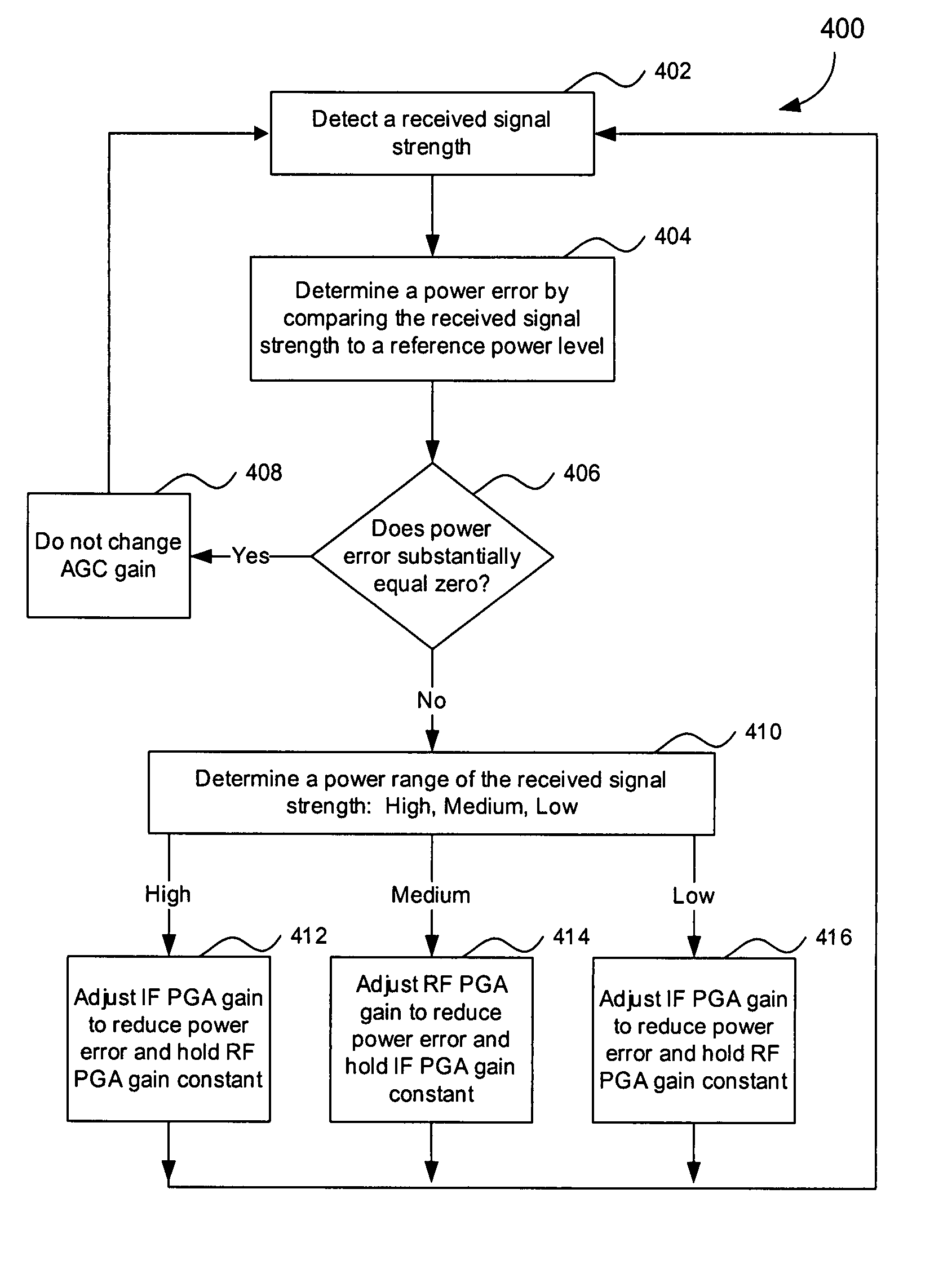
In an embodiment, a receiver for processing a RF input signal having a variable signal strength includes an RF amplifier, an IF amplifier, and a controller. The RF amplifier is configured to receive and amplify the RF input signal. The IF amplifier is coupled to an output of the RF amplifier. The controller controls gains of the RF amplifier and the IF amplifier during times of falling signal strength. A gain of the IF amplifier is increased as the signal strength falls until a first amplitude threshold is reached for the falling signal strength. If the signal strength falls beyond the first threshold, a gain of the RF amplifier is increased until a second amplitude threshold is reached. The second amplitude threshold is lower than the first amplitude threshold. If the signal strength falls below the second amplitude threshold, the gain of the IF amplifier is further increased.

Description

CROSS REFERENCE TO RELATED APPLICATIONS[0001]This application claims benefit of U.S. Provisional Patent No. 60 / 920,824 filed Mar. 30, 2007, which is incorporated by reference herein in its entirety.FIELD OF THE INVENTION[0002]The present invention is generally directed to communication systems. More particularly, the invention relates to Automatic Gain Control (AGC).BACKGROUND OF THE INVENTION[0003]A typical communication receiver includes several circuit blocks to process a received signal. The receiver has an antenna which receives a received signal containing a carrier signal that is modulated with a data signal. The received signal is initially amplified by a variable-gain radio frequency (RF) amplifier. After amplification, a mixer mixes the received signal with a local oscillator signal to down-convert the received signal to an IF or baseband signal. The output of the mixer is an intermediate frequency (IF) signal that is modulated with the data signal. A variable-gain IF ampl...

Claims


Application Information

Patent Timeline
Patent Type & Authority Patents(United States)
IPC IPC(8): H04B1/06
CPCH03G1/0088H03G3/3068
Inventor GOMEZ, RAMON ALEJANDROKRAFFT, STEPHENYU, TOMMY
Owner AVAGO TECH WIRELESS IP SINGAPORE PTE
Learn More