Check patentability & draft patents in minutes with Patsnap Eureka AI!

Condensation process and condenser

a condenser and condenser technology, applied in the field of condensers, can solve the problems of complicated physics of condensation of a mixture of gases, difficult measurement of condensation heat transfer, and inability to accurately estimate the performance of such condensers, and achieve the effect of improving performan

Inactive Publication Date: 2010-08-24
E S & A ROBINSON
View PDF9 Cites 1 Cited by
  • Summary
  • Abstract
  • Description
  • Claims
  • Application Information

AI Technical Summary

Benefits of technology

This approach improves the heat transfer process by reducing the air mass fraction adjacent to cooling surfaces, increasing the efficiency of condensers, allowing for smaller condenser designs, and enhancing the overall performance of steam condensation plants, leading to significant commercial benefits.

Problems solved by technology

Condensation heat transfer is however difficult to measure as it is a rapid and violent process in which a large quantity of heat is transferred through an interface across which the temperature difference is intentionally small.
This process, called inundation, complicates the estimation of the performance of such condensers and accordingly empirical correlations are generally used to predict the overall performance of such systems.
Whereas the physics of condensation of pure gases is relatively simple, the physics of condensation of a mixture of gases is considerably more complicated.
It appears however that the practical significance of this problem has been underestimated.
The presence of this air impedes the flow of more steam molecules to the surface of the water film.
The above problem has been discussed in the context of a plane vertical cooling surface, but generally condensers do not have such a simple structure and therefore inundation further complicates the estimation of the performance of the plants.
Nevertheless, although the principles of the processes have been understood for some time, it has not been possible readily to predict the rate at which the processes proceed with accuracy and therefore, in practical condensing plant, it has been conventional to rely upon empirical correlations when estimating the surface area required for a condenser heat exchanger.
Of course, a difficulty when relying upon empirical correlations is that it is not easy to predict the performance of a“perfect” plant so the extent of any short fall of performance may not be recognised.
Furthermore, if any of the correlations relied upon are not quite correct, the overall design cannot be optimum.

Method used


Image

  • Condensation process and condenser
  • Condensation process and condenser
  • Condensation process and condenser

Examples


Embodiment Construction

[0047]For the purposes of promoting an understanding of the principles of the invention, reference will now be made to the embodiments illustrated in the drawings and specific language will be used to describe the same. It will nevertheless be understood that no limitation of the scope of the invention is thereby intended, such alterations and further modifications in the illustrated device, and such further applications of the principles of the invention as illustrated therein being contemplated as would normally occur to one skilled in the art to which the invention relates.

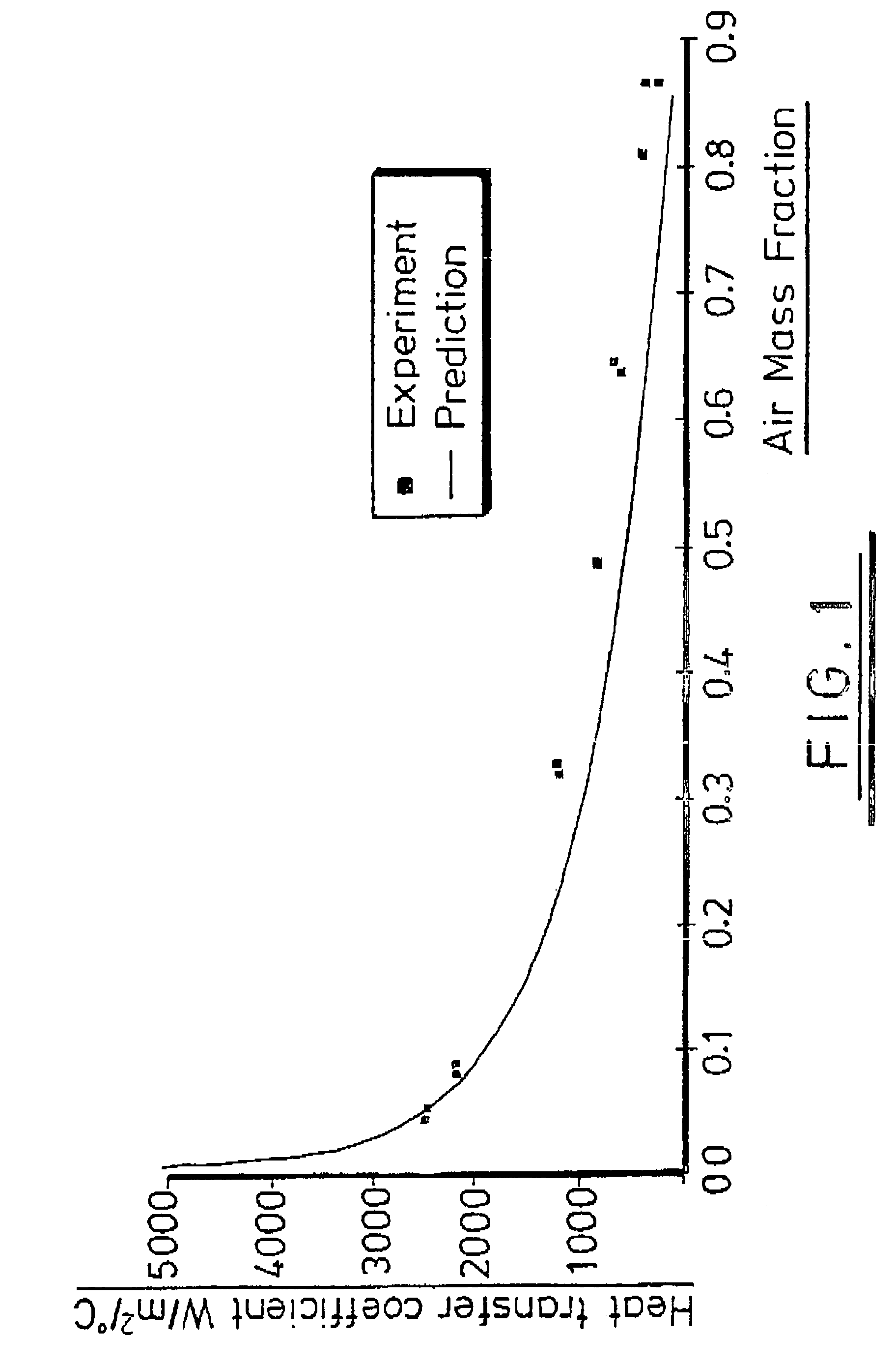
[0048]Referring to FIGS. 1 to 3, these present information derived from the accepted theory as discussed above and illustrating the effect of non-condensing gases on condensation processes. From FIG. 1 it can be appreciated that the heat transfer coefficient falls rapidly with increasing air mass fraction in a boundary layer between bulk gas and a film of condensate. FIG. 2 shows that the reduction in the heat ...


PUM

PropertyMeasurementUnit
temperatureaaaaaaaaaa
pressureaaaaaaaaaa
temperatureaaaaaaaaaa

Abstract

A condenser and a containment vessel adapted to efficiently condense a gas out of a mixture of condensing and non-condensing gases. In condensers, the fraction of gas within a condenser made up of non-condensing gases can be significantly reduced by withdrawing gas from localised regions of relatively low temperature where the mass fraction of non-condensing gases will be relatively high. In containment vessels, pressures can be reduced by providing a large surface area of the liquid into which the condensing gas condenses in a relatively cool region of the containment vessel. Both these effects result from an appreciation of the manner in which non-condensing gases tend to accumulate in regions which are relatively cold.

Description

CROSS-REFERENCE TO RELATED APPLICATIONS[0001]This application is a national filing from International Application No. PCT / GB2004 / 001511, filed 7 Apr. 2004. Applicants also claim foreign priority benefits under 35 U.S.C. §119 to U.K. Application GB0308657.6, filed 15 Apr. 2003. Both of these applications are incorporated herein by reference.FIELD OF THE INVENTION[0002]The present invention relates to condensers and methods for enhancing the efficiency of condensers. Various embodiments of the invention are applicable to the condensation of a first gas that is mixed with at least one second gas having a lower boiling point than the first gas. Various embodiments of the present invention are applicable in particular to steam condensers of the type used in electric power generation, but is also applicable in any circumstances in which a gas is being condensed from a mixture of gases.BACKGROUND OF THE INVENTION[0003]It has been well known for many years that the rate at which the gas in ...

Claims


Application Information

Patent Timeline
Patent Type & Authority Patents(United States)
IPC IPC(8): B01D53/00B01D5/00B01D53/26
CPCB01D5/0036B01D5/0093B01D53/002B01D53/265Y10S55/15Y10S165/207
Inventor ROBINSON
Owner E S & A ROBINSON
Features
  • R&D
  • Intellectual Property
  • Life Sciences
  • Materials
  • Tech Scout
  • Unparalleled Data Quality
  • Higher Quality Content
  • 60% Fewer Hallucinations
Learn More