System and method of compensating for system delay in analyte analyzation

a system delay and analyzation technology, applied in the field of system delay compensation and system delay compensation in analyzation, can solve the problems of system delay that is not adequately compensated, and other problems, to achieve the effect of reducing the number of errors

Inactive Publication Date: 2010-08-24
RIC INVESTMENTS LLC
View PDF4 Cites 8 Cited by
  • Summary
  • Abstract
  • Description
  • Claims
  • Application Information

AI Technical Summary

Benefits of technology

[0021]While the present invention is by no means limited to the use of LEDs, other advantages of implementing LEDs as emitter 12 include their light weight, compactness, low power consumption, low voltage requirements, low heat production, reliability, ruggedness, relatively low cost, and stability. Also LEDs can be switched on and off very quickly, reliably, and reproducibly.

Problems solved by technology

However, conventional systems may not adequately compensate for certain systematic errors introduced by their componentry.
The photosensitive detectors may introduce system delays that are not adequately compensated for by the conventional systems.
Other system components (such as and without limitation, amplifiers and filters) may also introduce delay.
These system delays may lead to inaccurate and / or imprecise determinations of information related to the gaseous analytes.

Method used


Image

  • System and method of compensating for system delay in analyte analyzation
  • System and method of compensating for system delay in analyte analyzation
  • System and method of compensating for system delay in analyte analyzation

Examples


Embodiment Construction

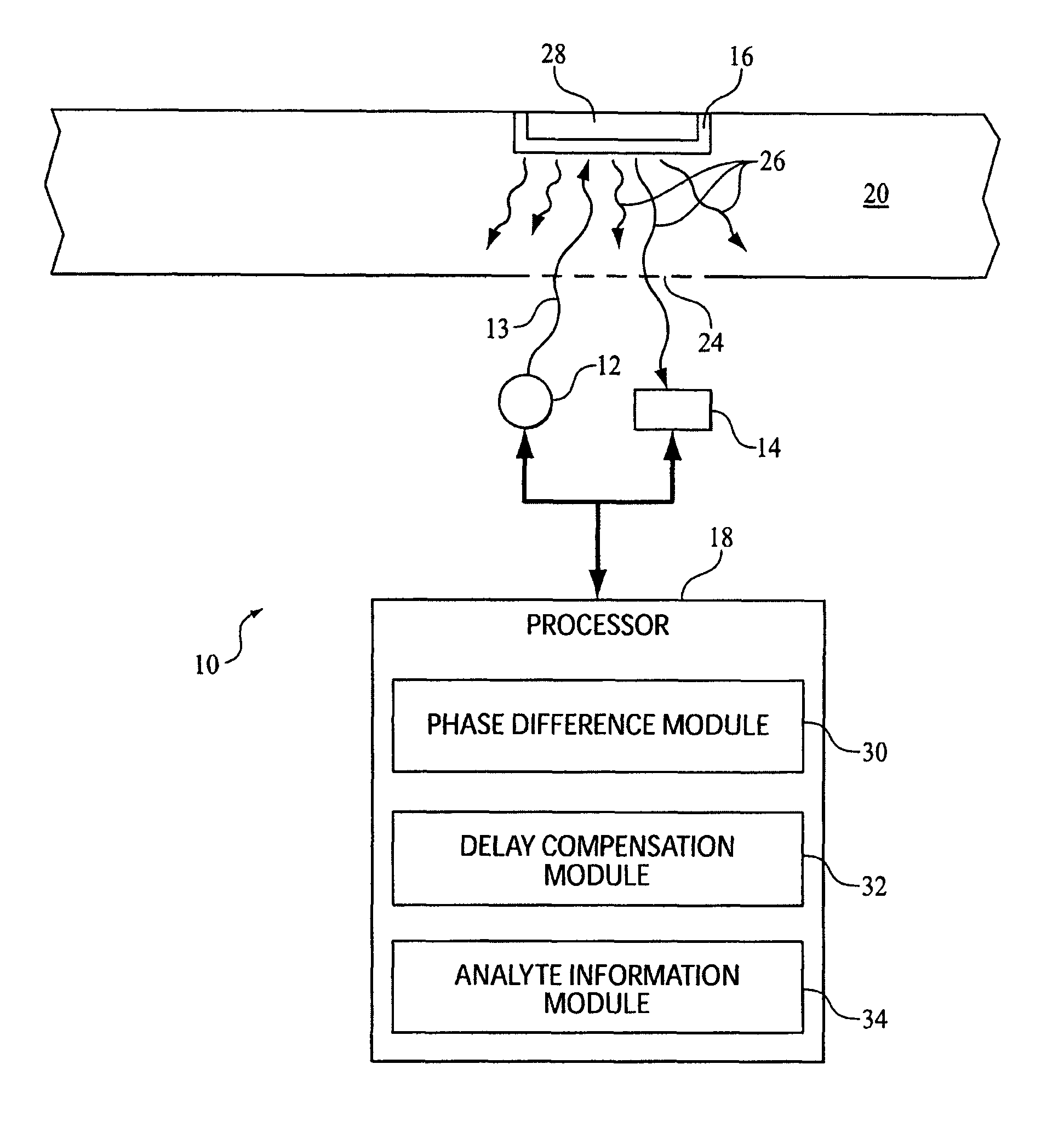
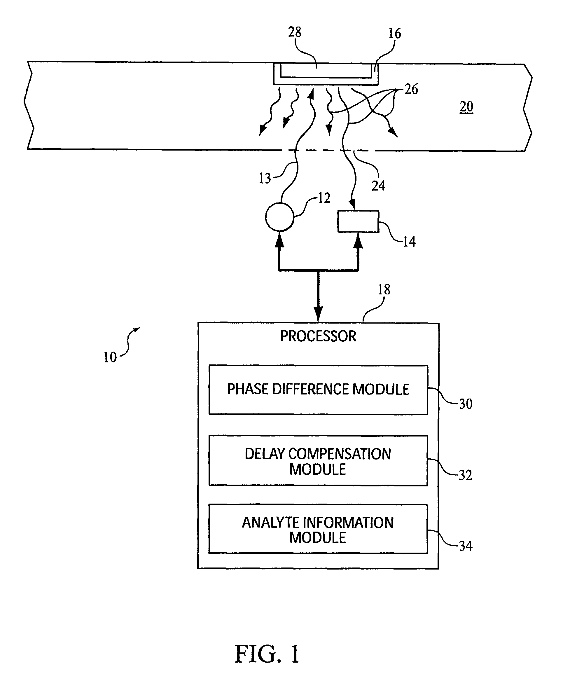
[0017]FIG. 1 illustrates a system 10 configured to determine information related to one or more gaseous analytes in a body of gas. System 10 includes one or more emitters 12, a photosensitive detector 14, a luminescable medium 16, and a processor 18. System 10 may determine information related to one or more gaseous analytes in the body of gas contained within a flow path 20. In one example, flow path 20 is defined by a conduit 22 adapted to carry gas to and / or from a patient. In a more particular example, conduit 22 may cooperate with a patient interface appliance configured to communicate with an airway of the patient. Some examples of the patient interface appliance may include, for example, an endotracheal tube, a nasal canula, a tracheotomy tube, a mask, or other patient interface appliances. The present invention is not limited to these examples, and contemplates determination of analytes in any body of gas.

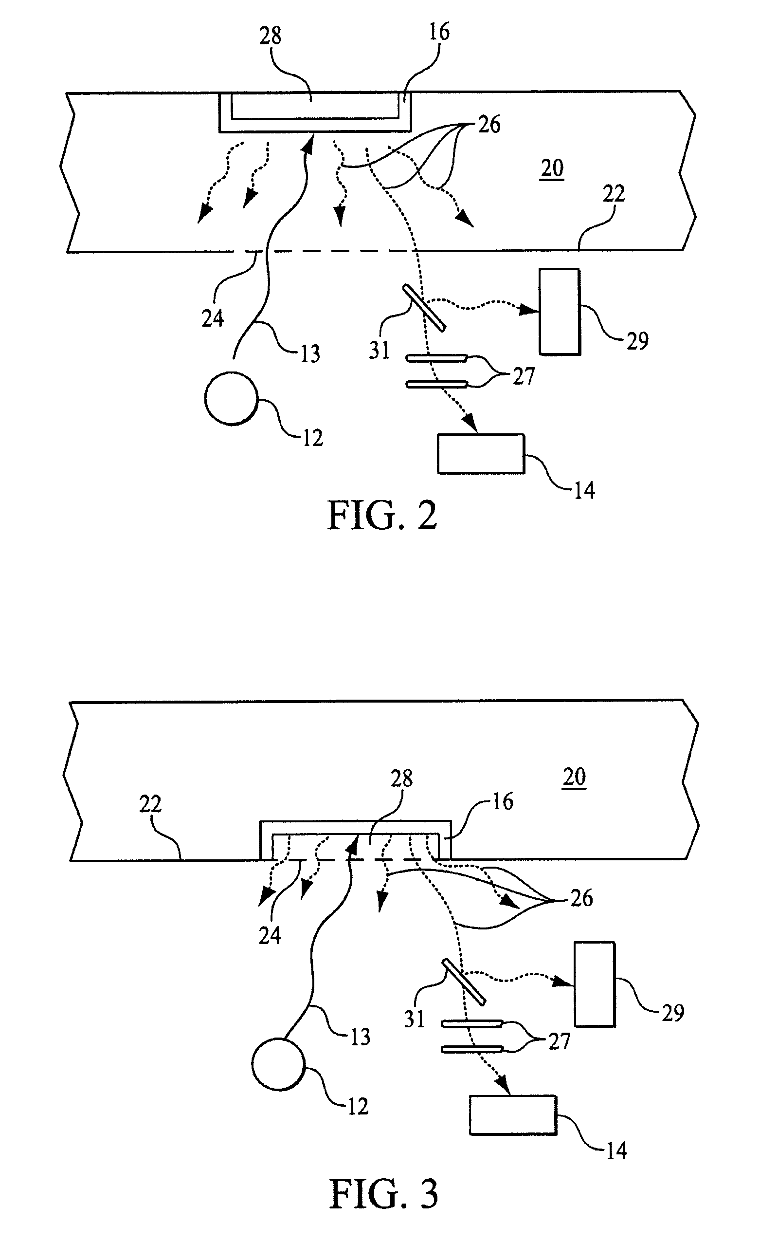
[0018]In some implementations, emitter 12, photosensitive detector 14,...


PUM

PropertyMeasurementUnit
luminescenceaaaaaaaaaa
phaseaaaaaaaaaa
concentrationsaaaaaaaaaa

Abstract

A system configured to determine information related to one or more gaseous analytes in a body of gas comprises a luminescable material, one or more emitters, one or more photosensitive detectors, and a processor. The emitters emit amplitude modulated electromagnetic radiation onto the luminescable medium in communication with a body of gas causing luminescence in the luminescable medium. The photosensitive detectors receive the amplitude modulated electromagnetic radiation generated by the luminescence of the luminescable medium and generate one or more output signals, at least one of the output signals indicating the intensity of the received electromagnetic radiation. The processor receives the output signals and determines information related to one or more gaseous analytes in the body of gas. The determination of information related to the one or more gaseous analytes may comprise compensating for a delay that varies as a function of the intensity of the received electromagnetic radiation.

Description

CROSS-REFERENCE TO RELATED APPLICATIONS[0001]This application claims priority under 35 U.S.C. §119(e) from provisional U.S. patent application No. 60 / 838,806 filed Aug. 18, 2006 the contents of which are incorporated herein by reference.BACKGROUND OF THE INVENTION[0002]1. Field of the Invention[0003]The invention relates generally to a system and method that determine information related to one or more gaseous analytes in a body of gas, and more particularly to adjusting for inaccuracies in the determination of such information.[0004]2. Description of the Related Art[0005]The use of luminescence-quenching detection to determine information related to gaseous analytes present in a body of gas is known. However, conventional systems may not adequately compensate for certain systematic errors introduced by their componentry. For example, photosensitive detectors are generally used by conventional systems to detect luminescence from a luminescable medium. The photosensitive detectors ma...

Claims


Application Information

Patent Timeline
Patent Type & Authority Patents(United States)
IPC IPC(8): G01N21/64G01N21/00B01J19/00B01J19/08
CPCA61B5/0833G01N21/6408A61B5/097Y10T436/20
Inventor MUELLER, CORD
Owner RIC INVESTMENTS LLC
Why Eureka
Try Eureka