
Electronic package with a thermal interposer and method of manufacturing the same

a technology of electronic packaging and thermal interposer, which is applied in the direction of electrical apparatus, semiconductor devices, semiconductor/solid-state device details, etc., can solve the problems of inadvertent loss of thermal heat energy in circuits, especially in temperature-sensitive circuits, and achieve the effect of preventing inadvertent transfer and reducing the amount of heat dissipation

Active Publication Date: 2010-08-24
GLOBALFOUNDRIES US INC
View PDF3 Cites 62 Cited by
  • Summary
  • Abstract
  • Description
  • Claims
  • Application Information

AI Technical Summary

Benefits of technology

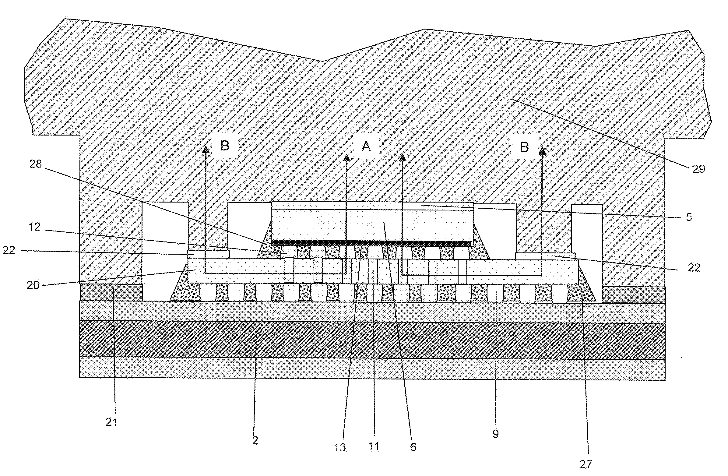
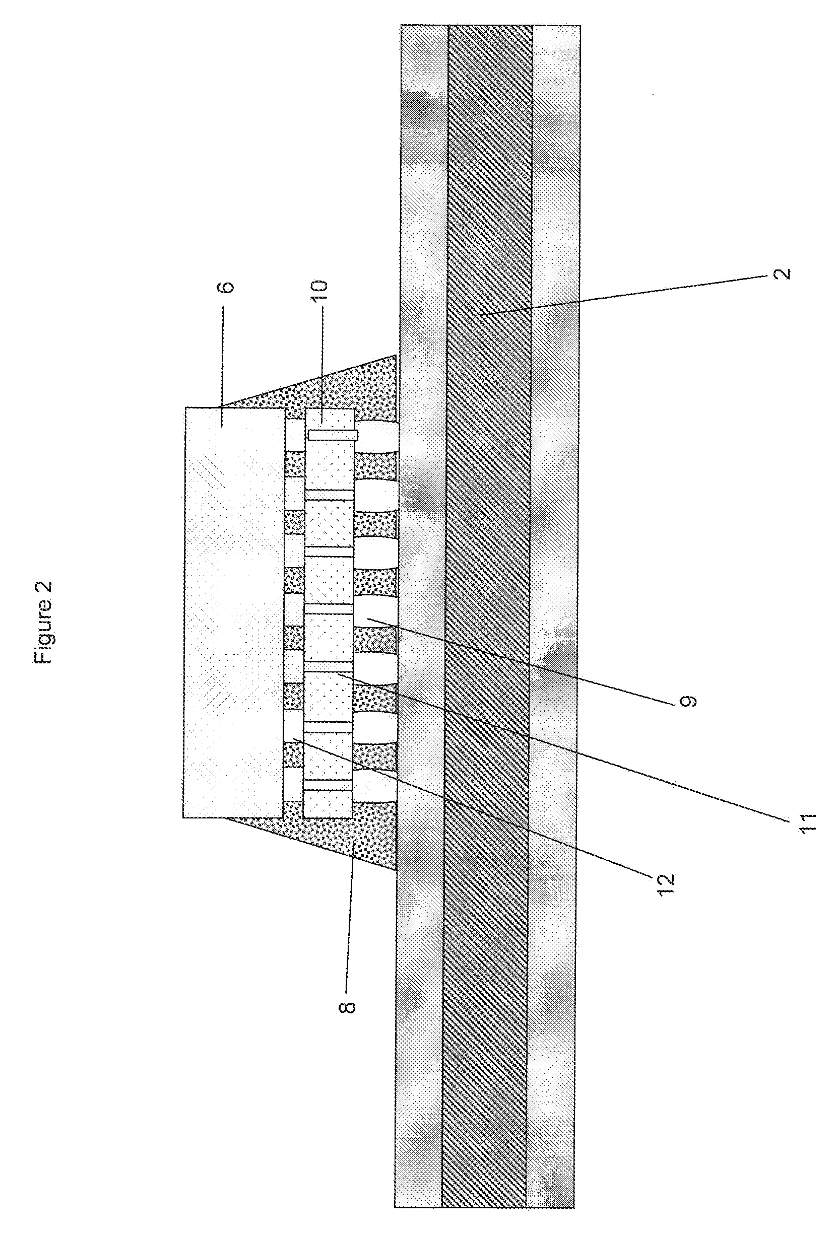
The present invention provides an electronic package with improved thermal resistance by using a thermal interposer with a primary heat flux path and an auxiliary heat flux path for conducting heat generated by a die. The thermal interposer has a high thermal conductivity and interfaces with the die and organic substrate through a thermal interface material. The thermal interposer can reduce the temperature at the periphery of the die and the device layer, allowing for the placement of temperature-sensitive circuits at the periphery. The invention also includes an augmenting element formed on the thermal interface material and a plurality of dies stacked three-dimensionally through which a primary heat flux path is enabled. The invention provides an improved thermal path for conducting heat from the die and reducing temperature-sensitive circuits.

Problems solved by technology

Achieving such thermal efficiency becomes more challenging as semiconductor electronics are being fabricated to provide a maximum amount of capability in as small a package or “footprint” as possible.
Due to the poor thermal conductivity of the organic substrate 2, the inadvertently lost (thermal) heat energy becomes trapped in circuits where additional heat energy is not desired.
Temperature-sensitive circuits especially suffer from this defect.
Conventional underfills are generally not good thermal conductors, but help to distribute the mechanical stresses away from C4 areas.
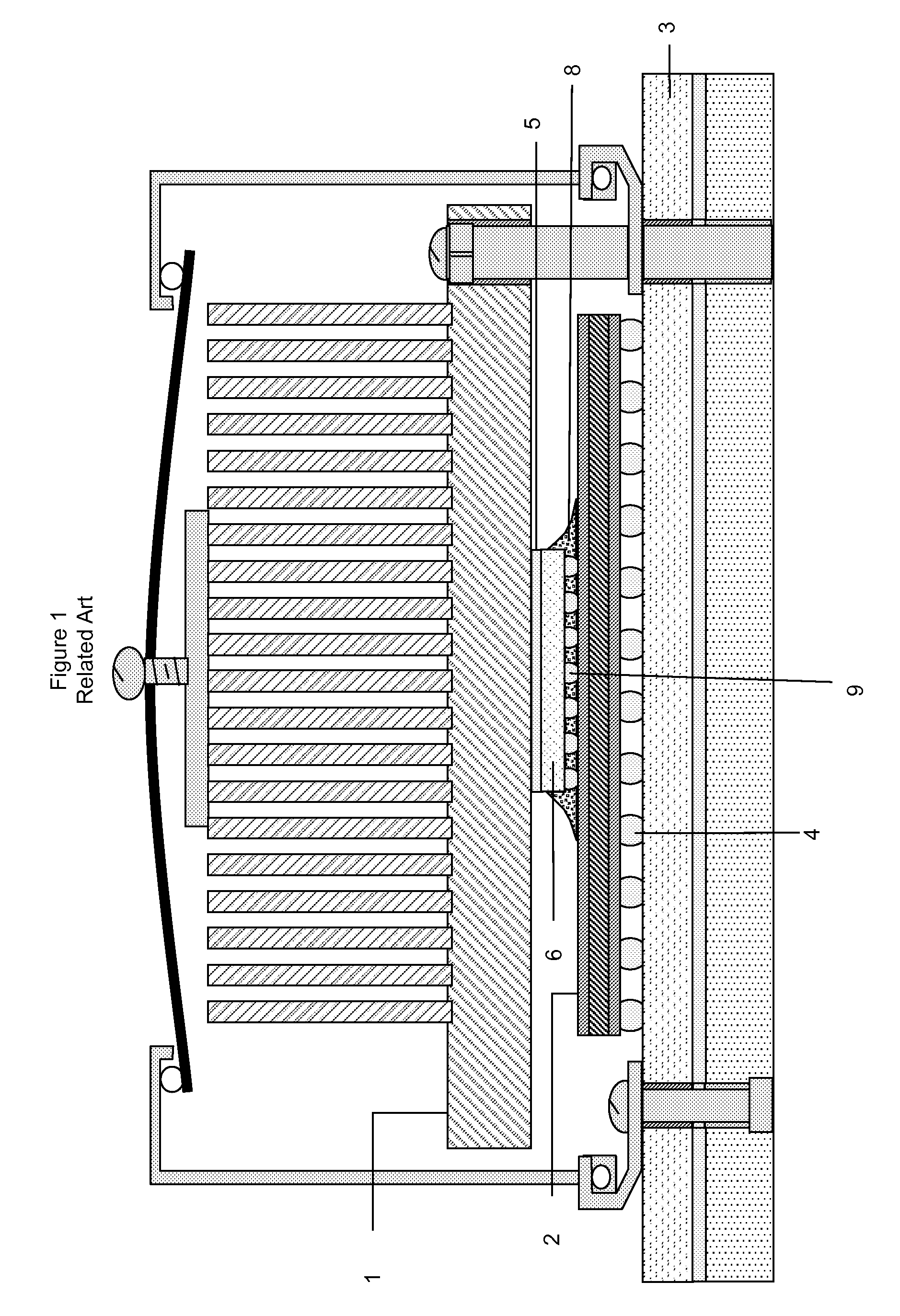
Nevertheless, as is shown in FIG. 5, despite all the mechanical benefits and advantages of including a conventional interposer in an electronic package, the conventional interposer fails to substantially contribute to a steady state thermal enhancement of the chip.
However, FIG. 5 shows that, despite the ability of the conventional interposer 10 to reduce stress associated with CTE in an electronic package, the conventional interposer 10 fails to positively influence conventional heat flux path A to reduce the amount of heat that is inadvertently lost and escaping through the bottom portion of the die.

Method used


Image

  • Electronic package with a thermal interposer and method of manufacturing the same
  • Electronic package with a thermal interposer and method of manufacturing the same
  • Electronic package with a thermal interposer and method of manufacturing the same

Examples


Embodiment Construction

[0058]Referring now to the drawings, and more particularly to FIGS. 6-10, there are shown exemplary embodiments of the structures and method according to the present invention.

[0059]The present invention serves to address and limit the inadvertent transfer of heat to unwanted areas, such as electronic connections. Heat energy not transferred out of an upper surface of a die was conventionally inadvertently transferred to areas where increases in heat energy were unwanted, such as areas of electronic connection.

[0060]Further, the heat energy conventionally inadvertently transferred to unwanted areas was conventionally further trapped and restricted to these unwanted areas by multi-layer organic substrates that are conventionally and presently designed to be relatively poor conductors. Thus, the inadvertently transferred heat energy has no escape from the areas in which heat energy was least desired.

[0061]As previously mentioned, conventional interposers have been normally used only t...


PUM

PropertyMeasurementUnit
diagonal distanceaaaaaaaaaa
shear stressaaaaaaaaaa

Abstract

An electronic package includes a die including a thermal interface material through which a primary heat flux path is enabled for conducting heat from the die, an organic substrate, and a thermal interposer provided between the organic substrate and the die, the thermal interposer having an area extending beyond a footprint of the die, the area including the thermal interface material, the thermal interposer conducting heat generated by the die through the thermal interface material such that an auxiliary heat flux path for conducting heat generated in the die is enabled.

Description

BACKGROUND OF THE INVENTION[0001]1. Field of the Invention[0002]The present invention generally relates to an electronic package with a thermal interposer, and more specifically to an electronic package where a thermal interposer provides an improved thermal resistance and retains the mechanical advantages of a conventional interposer.[0003]2. Description of the Related Art[0004]Thermal efficiency is critical to achieving higher performance in computer chips. Achieving such thermal efficiency becomes more challenging as semiconductor electronics are being fabricated to provide a maximum amount of capability in as small a package or “footprint” as possible. In order to prevent temperature-sensitive circuits from being negatively affected by high thermal conditions, various cooling systems have been implemented in association with electronic packages.[0005]FIG. 1 shows elements of a conventional electronic package integrated with a cooling solution. In FIG. 1, a vapor chamber heat sin...

Claims


Application Information

Patent Timeline
Patent Type & Authority Patents(United States)
IPC IPC(8): H01L23/34
CPCH01L23/10H01L23/367H01L23/49816H01L25/0657H01L23/42H01L23/427H01L23/4338H01L24/16H01L24/31H01L2023/4081H01L2224/73253H01L2225/06517H01L2225/06589H01L2924/01019H01L2924/3512H01L2924/00H01L2924/00014H01L2924/00011H01L2224/16227H01L2224/16235H01L2224/32225H01L2224/73204H01L2924/15311H01L2924/1615H01L2924/16251H01L2924/3511H01L2224/0401H01L2224/16225
Inventor SRI-JAYANTHA, SRI M.MCVICKER, GERARDKNICKERBOCKER, JOHN U.
Owner GLOBALFOUNDRIES US INC
Learn More