High speed differential to single ended converting circuit

a conversion circuit and high-speed differential technology, applied in the direction of differential amplifiers, amplifiers with semiconductor devices/discharge tubes, amplifiers with semiconductor devices only, etc., can solve the problems of common-mode drift of output voltage vout, conversion circuits which comprise load devices, and require more power consumption

Active Publication Date: 2010-08-24
FARADAY TECH CORP
View PDF6 Cites 4 Cited by
  • Summary
  • Abstract
  • Description
  • Claims
  • Application Information

AI Technical Summary

Problems solved by technology

The different numbers of transistor the differential currents in and ip flow leads to the mismatch of the differential currents in and ip which results in jitter and common-mode drift of the output voltage Vout.
The transistor 62 is thus prevented from turning off so that the operation speed of the conversion circuit is up, However, the conversion circuit which comprises the load device requires more power consumption.

Method used


Image

  • High speed differential to single ended converting circuit
  • High speed differential to single ended converting circuit
  • High speed differential to single ended converting circuit

Examples


Embodiment Construction

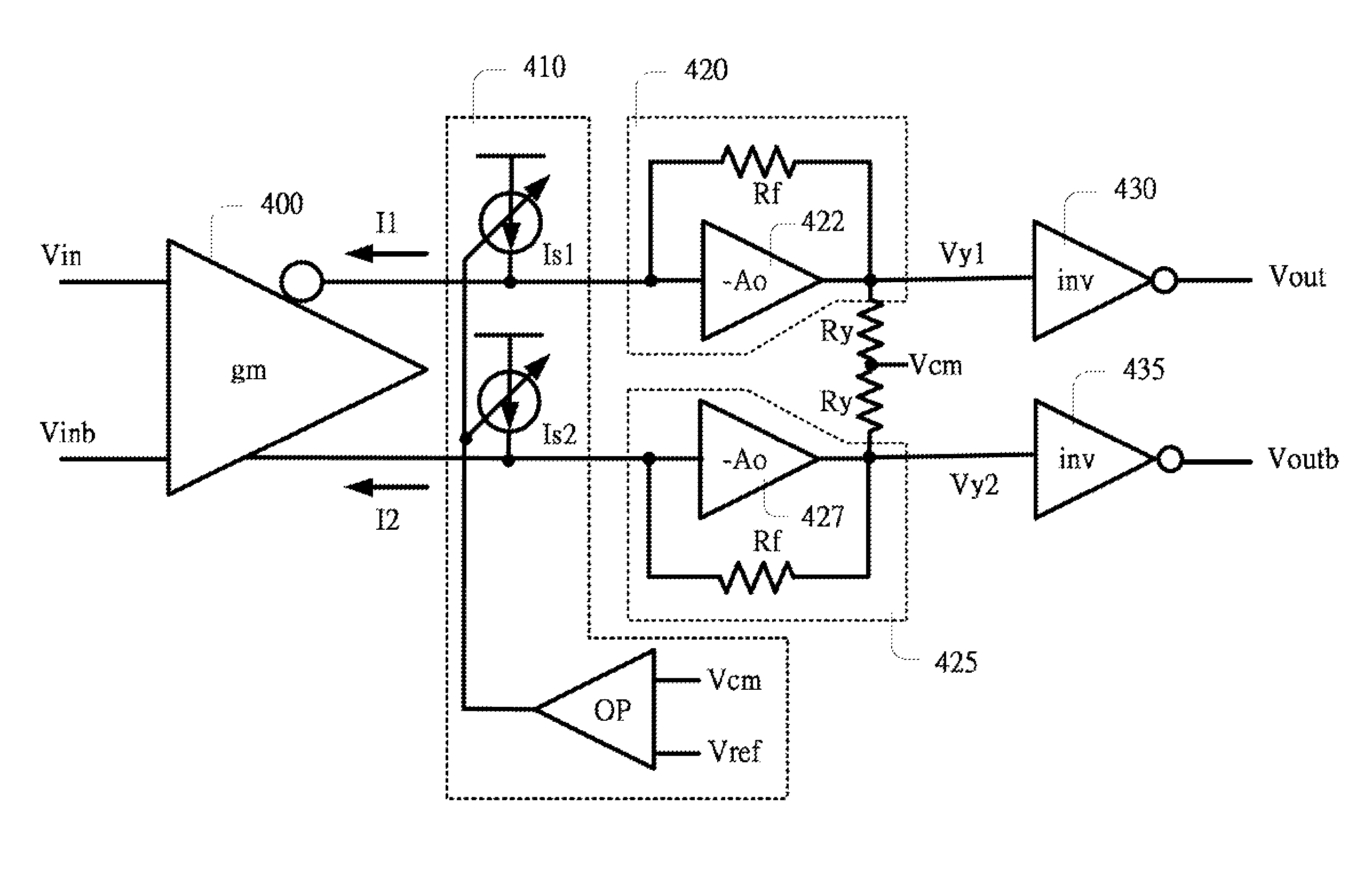
[0023]Refer to FIG. 4, which illustrates a differential to single ended converting circuit according to the present invention. The differential to single ended converting circuit comprises a transconductance circuit 400, an offset cancellation circuit 410, a first transimpedance circuit 420, a second transimpedance circuit 435, a firs inverter 430 and a second inverter 435.

[0024]The first transimpedance circuit 420 and the second transimpedance circuit 425 are totally the same in structure and are shut-shut feedback amplifier. In addition, the first transconductance circuit 420 comprises an amplifying unit 422 and a feedback resistance Rf wherein the amplifying unit 422 has an −Ao open loop gain and the feedback resistance Rf is connected between the input terminal and the output terminal of the amplifying unit 422. In the same way, the second transconductance circuit 425 comprises an amplifying unit 427 and a feedback resistance Rf wherein the amplifying unit 427 has an −Ao open lo...


PUM


Abstract

A differential to single ended converting circuit includes a transconductance circuit having input terminals for receiving differential input voltages and having a first current output terminal for outputting a first current and a second current output terminal for outputting a second current; an offset cancellation circuit having a first controllable current source connected to the first current output terminal and a second controllable current source connected to the second current output terminal; a first transimpedance circuit having an input terminal connected to the first current output terminal and an output terminal for outputting a first voltage; a second transimpedance circuit having an input terminal connected to the second current output terminal and an output terminal for outputting a second voltage; and a first inverter having an input terminal connected to the output terminal of the first transimpedance circuit and an output terminal for outputting a first single ended output voltage.

Description

FIELD OF THE INVENTION[0001]The present invention relates to a signal converting circuit, and more particularly to a high speed differential to single ended converting circuit.BACKGROUND OF THE INVENTION[0002]Refer to FIG. 1, which illustrates a conventional differential to single ended converting circuit. The differential to single ended converting circuit comprises a first p type transistor mp1, having a source connected to a voltage source Vdd, a gate and a drain which are connected to each other, a first n type transistor mn1, having a drain connected to the drain of the first p type transistor mp1, and a source connected a current source I, a second p type transistor mp2, having a source connected to the voltage source Vdd, a gate and a drain which are connected to each other, and a second n type transistor mn2, having a drain connected to the drain of the first p type transistor mp2. In addition, the gate of the first n type transistor mn1 and the gate of the second n type tra...

Claims


Application Information

Patent Timeline
Patent Type & Authority Patents(United States)
IPC IPC(8): H03F3/04
CPCH03F3/3028H03F3/45179H03F3/45183H03F3/45206H03F3/45475H03F3/45511H03F3/45928H03F2200/411H03F2203/30031H03F2203/45082H03F2203/45418H03F2203/45424H03F2203/45642H03F2203/45646H03F2203/45674H03F2203/45676
Inventor LIN, INN-FUHSIUNG, WEN-CHING
Owner FARADAY TECH CORP
Why Eureka
Try Eureka