Optimal encoding of motion compensated video

a technology of motion compensation and video encoding, applied in the field of video encoding, can solve the problems of inability to move these large streams of video data across digital networks or phone lines, and require a large volume of data to describe one pixel, so as to reduce time delay

Inactive Publication Date: 2010-08-24
ORACLE INT CORP
View PDF23 Cites 8 Cited by
  • Summary
  • Abstract
  • Description
  • Claims
  • Application Information

AI Technical Summary

Benefits of technology

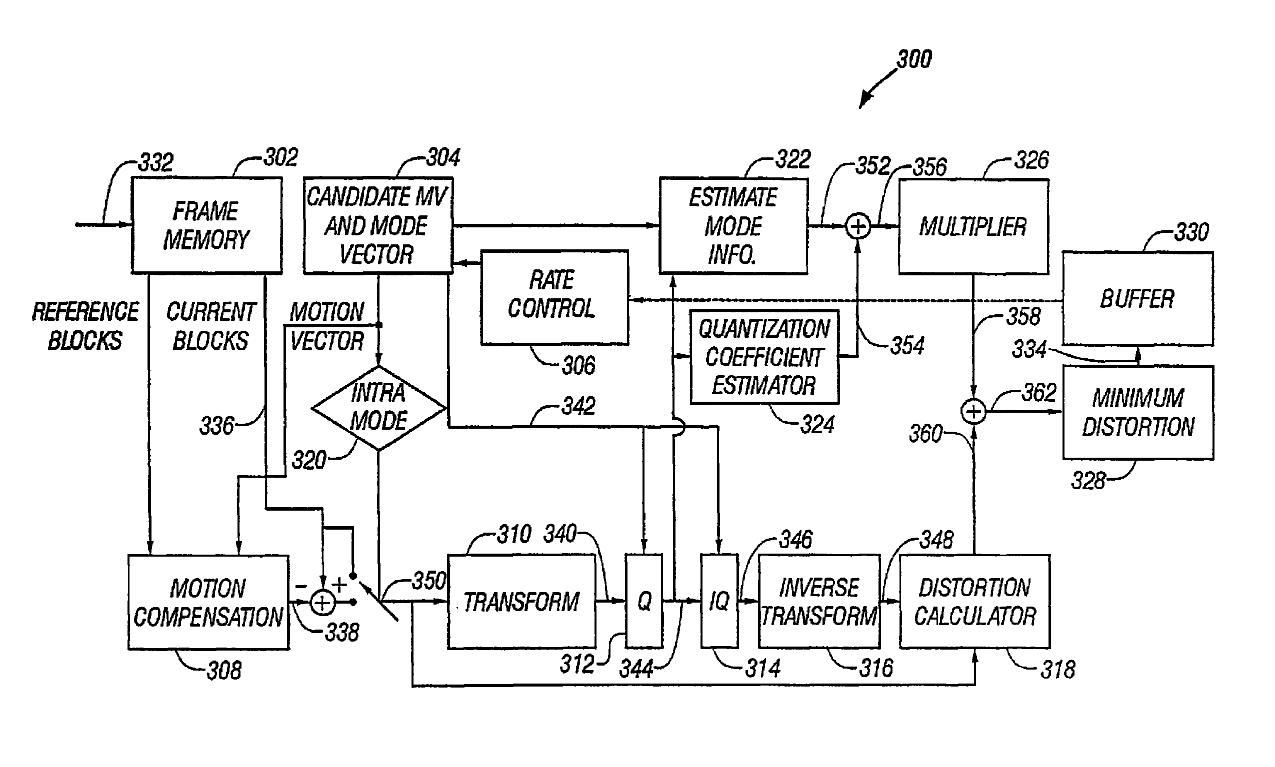
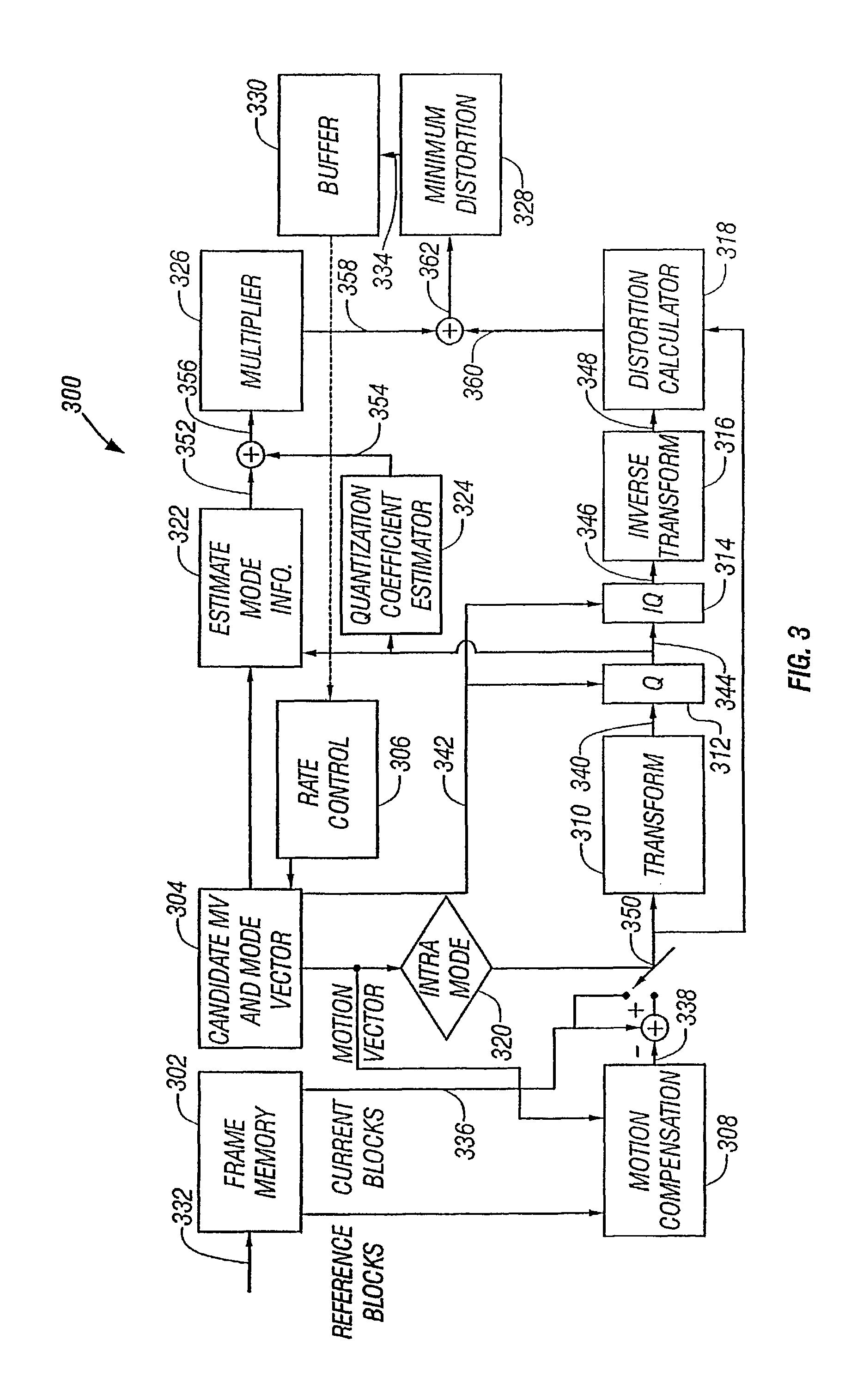
[0013]A Lagrange multiplier may be used to determine the bit-rate term in (b). The bit stream associated with the selected motion vector and corresponding mode vector includes the quantized discrete cosine transform coefficients, the motion vectors, and the mode vector encoded in a compressed format. The bit stream is output to an output buffer. The motion estimation signal may also be based on the measure of distortion, the bit-rate term, and the quantization parameter. Further, selected processes in the method may be executed in parallel to decrease time delay.

Problems solved by technology

Thus, a fairly large volume of data is required to describe one pixel.
Moving these large streams of video data across digital networks or phone lines is infeasible given currently available bandwidth.

Method used


Image

  • Optimal encoding of motion compensated video
  • Optimal encoding of motion compensated video
  • Optimal encoding of motion compensated video

Examples


Embodiment Construction

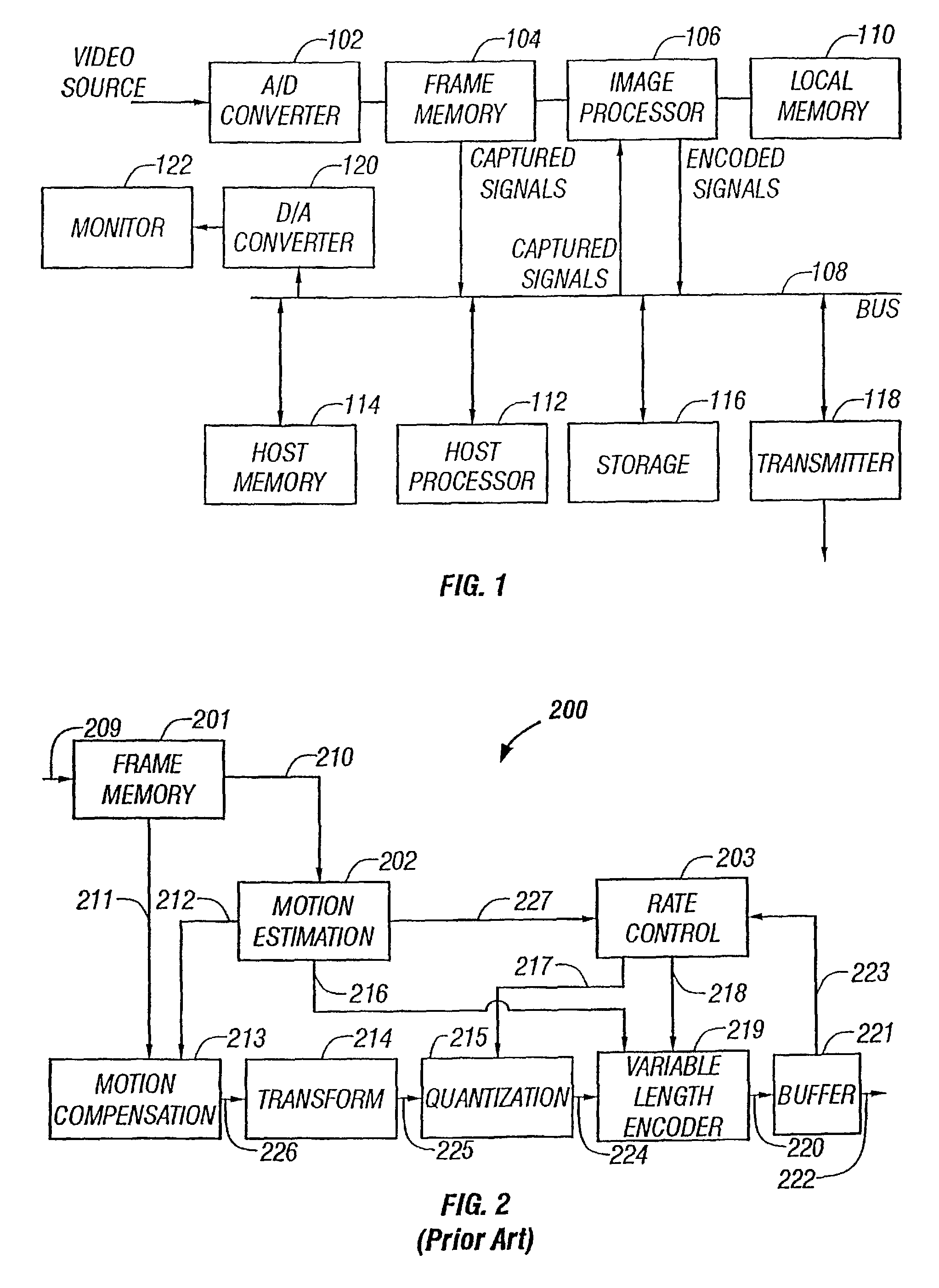
[0020]As the present invention may be applied in connection with an encoder meeting the industry standards, some pertinent aspects of standard compression algorithms will be reviewed. It is to be noted that the invention can be applied to video coding algorithms which share some of the following features.

[0021]It will be understood that the compression of any data object, such as a page of text, an image, a segment of speech, or a video sequence, can be broken into a series of steps, including 1) decomposing the object into a collection of tokens; 2) representing the tokens by binary strings which have minimal length in some sense; and 3) concatenating the strings in a well-defined order. Steps 2 and 3 are lossless, i.e., the original data is faithfully recoverable upon reversal. Step 1 can be either lossless or lossy in general. Most video compression schemes are lossy because of stringent bit-rate requirements. A successful lossy compression algorithm eliminates redundant and irre...


PUM


Abstract

Both distortion rate and bit-rate can be considered together when selecting a lowest cost motion estimation signal. A motion estimation signal is generated for each of the candidate motion vectors and candidate mode information vectors for a macroblock. An estimated amount of encoding bits is determined for each of the candidate motion vectors, candidate mode information vectors, and quantized coefficients. A bit-rate is computed based on the estimated amount of encoding bits. In addition, a current macroblock is reconstructed with each of the candidate vectors, and distortion measured between each of the reconstructions and the current macroblock. A sum is computed for each distortion measurement and corresponding bit-rate. The lowest sum represents the lowest cost motion estimation signal.

Description

CROSS-REFERENCE TO RELATED PATENT APPLICATIONS[0001]This non-provisional patent application is a continuation application that claims benefit under 35 U.S.C. §120 of U.S. patent application Ser. No. 10 / 156,992, filed on May 29, 2002 and naming Parthasarathy Sriram and Subramania Sudharsanan as inventors. U.S. patent application Ser. No. 10 / 156,992 is a continuation of U.S. patent application Ser. No. 09 / 238,878, filed on Jan. 27, 1999, naming Parthasarathy Sriram and Subramania Sudharsanan as inventors.BACKGROUND OF THE INVENTION[0002]1. Field of the Invention[0003]This invention relates to the field of video encoding, and more particularly relates to motion estimation in video encoding.[0004]2. Description of the Related Art[0005]To represent a picture image digitally, the image area is described as an array of pixels. A digital number describes the color, luminance and chrominance of each pixel. Pixel color information consists of three digital values: one digital value for red, o...

Claims


Application Information

Patent Timeline
Patent Type & Authority Patents(United States)
IPC IPC(8): H04B1/66H04N7/26H04N7/50
CPCH04N19/56H04N19/176H04N19/147H04N19/51H04N19/61H04N19/567H04N19/107H04N19/136H04N19/137H04N19/19H04N19/103
Inventor SRIRAM, PARTHASARATHYSUDHARSANAN, SUBRAMANIA
Owner ORACLE INT CORP
Why Eureka
Try Eureka