Sensor localization using lateral inhibition

a technology of lateral inhibition and sensor, applied in the direction of instruments, computer control, process and machine control, etc., can solve the problems of consuming significant power, unable to use pre-determined sensor locations, and using multiple base stations and high-frequency transmitters and receivers that are expensive and expensive, so as to facilitate lateral inhibition and increase the spatial resolution of a position.

Active Publication Date: 2010-08-24
ORACLE INT CORP
View PDF10 Cites 105 Cited by
  • Summary
  • Abstract
  • Description
  • Claims
  • Application Information

AI Technical Summary

Benefits of technology

[0011]In some embodiments, during the first mode of operation dimensions of a border of a region that includes the devices may be determined based on strengths of the communication signals. And during the second mode of operation, the position of an object may be determined based on sensor measurements performed by the devices and strengths of the communication signals in the first mode of operation and in the second mode of operation. For example, the dynamic adjustment of the strength may facilitate lateral inhibition to increase a spatial resolution of a position of the object determined by the devices.

Problems solved by technology

However, the use of pre-determined sensor locations is not possible in an increasingly popular category of sensor networks that allow random or ad hoc sensor placement.
While there are many existing localization techniques that may be used in sensor networks, these approaches are often unattractive due to additional system constraints, such as power requirements, limitations on onboard resources (for example, the processor speed or the amount of memory), cost, as well as maintenance and reliability restrictions.
However, this technique uses multiple base stations as well as high-frequency transmitters and receivers that are expensive and consume significant power.
Unfortunately, effects such as noise, interference, multi-path signals, and the difficulty of determining strength changes at very close range have limited the efficacy of this technique.
Furthermore, allowing random sensor positions may have consequences for the spatial resolution of measurements performed by sensors in an ad hoc sensor network.
When the sensor placement, and thus the sensor density, is random, it may therefore be difficult to achieve a desired or optimal spatial resolution from the array.

Method used


Image

  • Sensor localization using lateral inhibition
  • Sensor localization using lateral inhibition
  • Sensor localization using lateral inhibition

Examples


embodiment 200

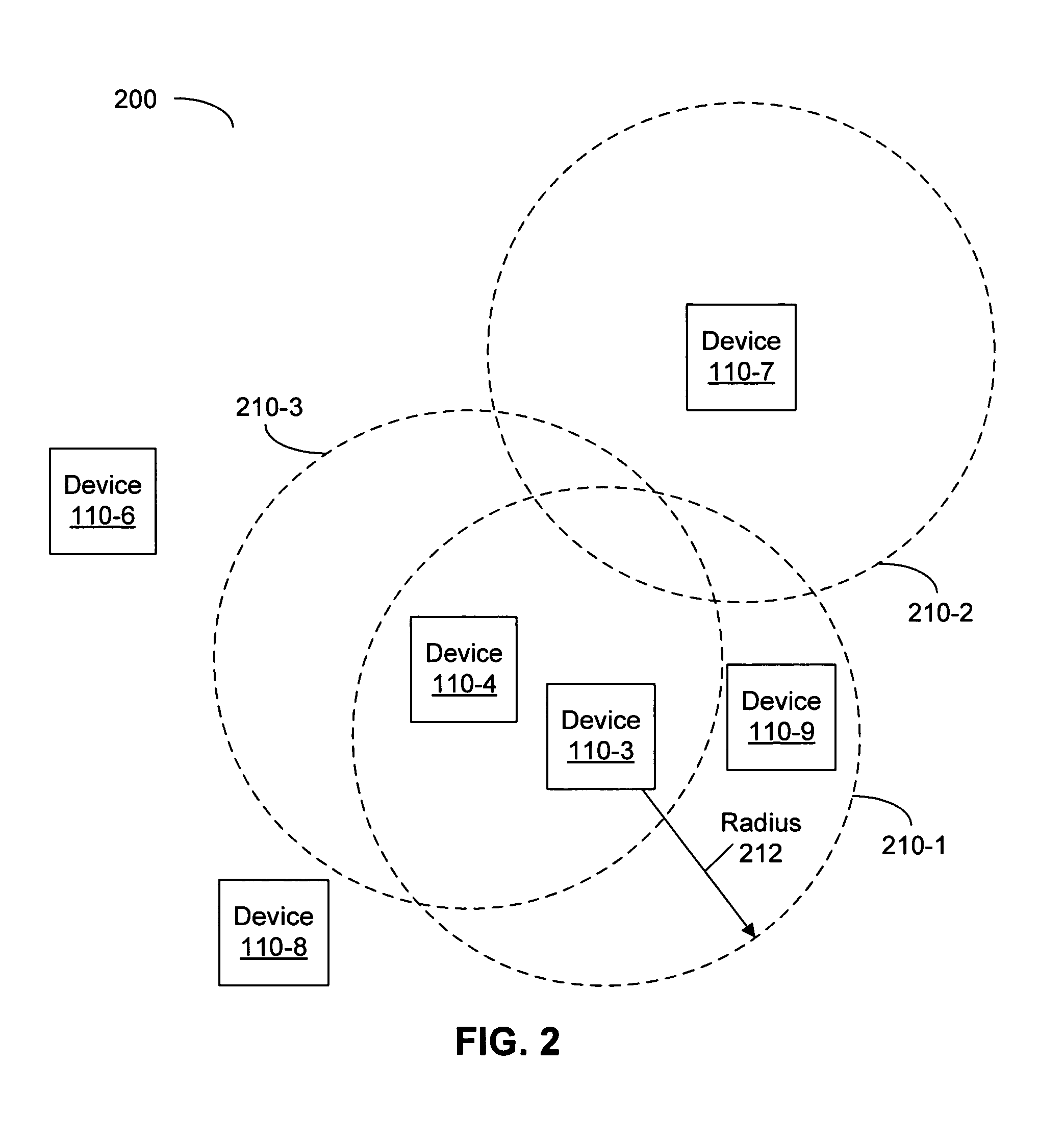
[0044]FIG. 2 is a block diagram illustrating an embodiment 200 of communication between devices 110 in the array. As discussed above, the given device may communicate with other devices within the pre-determined distance. For example, the device 110-3 may communicate with device 110-4 and 110-9 that are within a region 210-1 of radius 212. Other devices 110 have corresponding regions 210 of communication. The radius 212 may, at least in part, be determined by the strength of the communication signal(s) transmitted by the device 110-3. For example, if the strength corresponds to an intensity or power, the region 210-1 of effective communication is proportional to an inverse of the radius 212 to the nth power, where n may be between 2 and 3. In other embodiments, the strength is a magnitude of an amplitude of the communication signal.

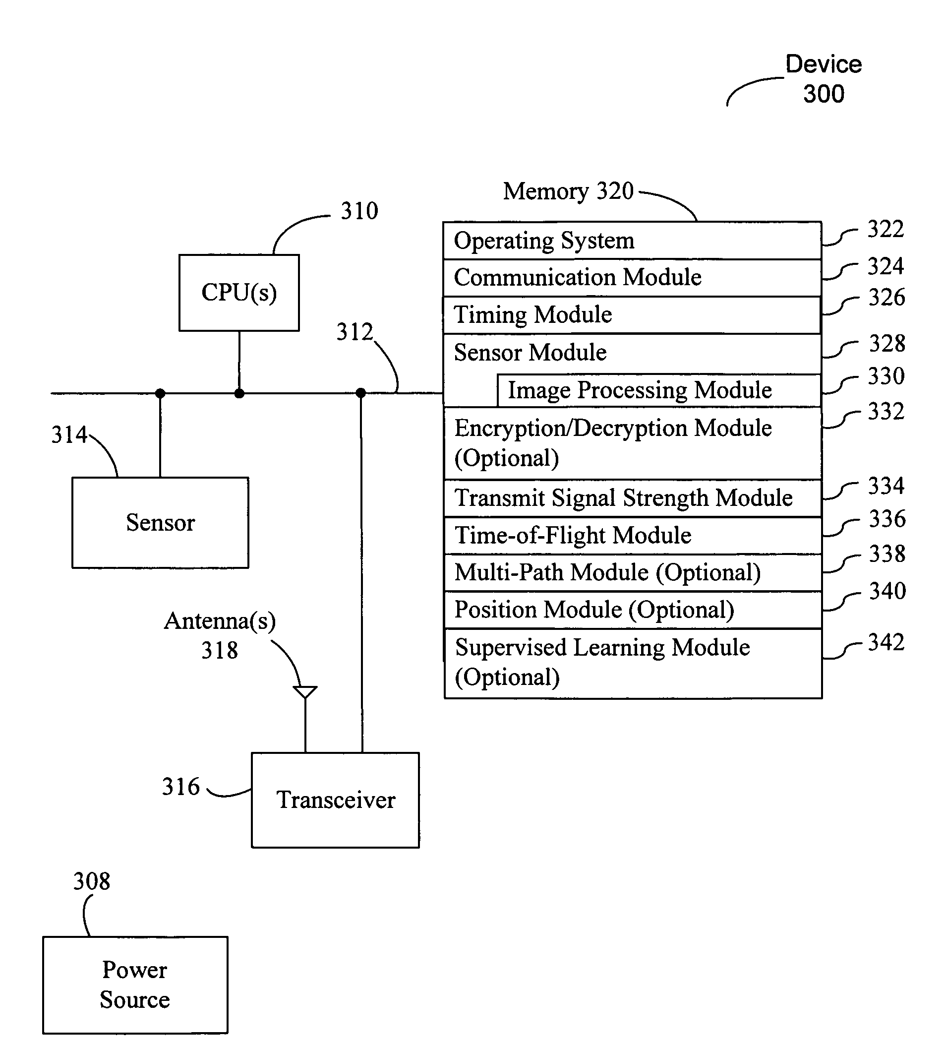
[0045]FIG. 3 is a block diagram illustrating an embodiment of a device 300 (such as one of the devices 110 in FIG. 1), which includes one or processors 3...

embodiment 600

[0062]We now discuss illustrative embodiments of the method and system that utilize lateral inhibition. FIG. 6A is a block diagram illustrating an embodiment 600 of strengths of communication signals from devices in an ordered array at the start of the calibration mode of operation. As indicated by the uniform (white) shading 610-1 of the devices, the strengths of the communication signals from the devices are initially the same.

embodiment 650

[0063]As illustrated in embodiment 650 in FIG. 6B, the devices may modify the strengths of the communication signals based on signals received from other devices. For example, strengths of the communication signals may be modified based on the strengths of received signals. Devices that have more neighbors or that are closer to the center of the array have lower strengths. As a consequence, the strengths of the communication signals vary across the array. This is illustrated by shadings 610. Note that the strength is largest at the border of the array and smallest at the center. Furthermore, in some embodiments the strengths may have a discrete distribution (such as that associated with quantized bins) or a continuous distribution.

[0064]Thus, the strengths of the communication signals provide relative position information, such as where the given device is in the array. In addition, the strengths of the communication signals determine the border of the array. This information may be...


PUM


Abstract

A system including multiple devices that each have a sensor and are each configured to communicate with other devices. The system further includes a controller configured to provide command information that specifies a mode of operation of the devices. In a first mode of operation, the devices transmit communication signals and a given device modifies a strength of its communication signal from an initial strength to a final strength based on communication signals it receives from one or more other devices. And in a second mode of operation, the devices transmit communication signals and the given device dynamically adjusts a strength of its communication signal based communication signals it receives from one or more other devices and on measurements performed by the sensor in the given device.

Description

BACKGROUND[0001]1. Field of the Invention[0002]The present invention relates to techniques for determining sensor positions and improving the spatial resolution of measurements performed with these sensors. More specifically, the present invention relates to arrays of sensors that utilize lateral inhibition when communicating with one another.[0003]2. Related Art[0004]Many measurement and monitoring systems include distributed arrays of interacting sensors, which are also known as sensor networks. For example, sensor networks are used to perform measurements of parameters such as temperature and humidity or to monitor intrusion across virtual borders in a variety of environments. In order to provide useful information in these applications, the locations of the sensors often need to be known or inferred. However, the use of pre-determined sensor locations is not possible in an increasingly popular category of sensor networks that allow random or ad hoc sensor placement. In these net...

Claims


Application Information

Patent Timeline
Patent Type & Authority Patents(United States)
IPC IPC(8): H03F1/26G08B1/08H04B1/10H04B7/00H04B1/04H04B1/00G05B15/00G06F15/18
CPCG08B25/009G08B25/10G08B25/007
Inventor CUNNINGHAM, HELEN A.
Owner ORACLE INT CORP
Why Eureka
Try Eureka