
Isolation platform

a technology of isolation platform and isolation bearing, which is applied in the direction of shock-proofing, machine supports, mechanical equipment, etc., can solve the problems of affecting and further reducing the service life of the platform

Active Publication Date: 2010-08-31
WORKSAFE TECHNOLOGY INC
View PDF35 Cites 19 Cited by
  • Summary
  • Abstract
  • Description
  • Claims
  • Application Information

AI Technical Summary

Benefits of technology

"The present invention provides a platform for isolating equipment or structures from vibrations. The platform consists of upper and lower plates with conical depressions and rigid spherical bearings placed between them. When lateral forces are applied, the platform dislocates and dampens the vibrations. The size of the platform's footprint and the retaining mechanisms can increase stability. The platform can also include a cavity containing rigid balls to provide additional damping. The first and second open pan structures can be movably fastened together with straps that limit displacement in both vertical and horizontal directions. The platform can move in the horizontal plane without moving in the vertical plane and can be designed to move at a pre-selected force."

Problems solved by technology

Presently known metallic yielders, however, are disadvantageous in that they inhibit or even prevent effective vertical isolation, particularly in assemblies wherein the metallic yielder is connected to both the upper bearing plate and the oppositely disposed lower bearing plate within which the rubber bearing body is sandwiched.
Presently known seismic isolation bearings are further disadvantageous inasmuch as it is difficult to separate the viscous and hysteretic damping characteristics of a high damping rubber bearing; a seismic isolation bearing is thus needed which effectively decouples the viscous and hysteretic functions of the bearing.
Steel spring mounts of the type typically used in conjunction with machines are unable to provide energy dissipation, with the effect that such steel spring mounts generally result in wide bearing movements.
However, in use, the snubber may impart to a machine an acceleration on the order of or even greater than the acceleration applied to the machine due to seismicity.
However, it is difficult to control or maintain the friction coefficient associated with such isolators; furthermore, such isolators typically do not provide vertical isolation, and are poorly suited for use in applications wherein an uplift capacity is desired.
However, such devices are not without their own drawbacks.
For example, depending on their size, they may have a limited range of mobility.
That is, the amount of displacement between the upper and lower plates may be limited based on the size of the bearing.
Additionally, the bearing structures may be unstable by themselves.
For example, when a large structure is placed on a relatively small bearing, it may become more likely that the structure could Up and / or fall over.
Obviously, with very large, heavy structures, such failure could be catastrophic.
Similar to instability, the amount of load that any particular bearing structure can withstand can be limited by its size.
Likewise, also related to the instability of the bearing, should the weight of the structure being supported be unevenly distributed, one section of either of the upper or lower plates may tend to bend or deflect more than another and the entire bearing structure could come apart.
Further still, often, when such large structures such as servers, electron microscopes, or other sensitive equipment are to be installed, the buildings and areas into which they are going to be installed are not easily configured to accommodate bearings such as those described above.

Method used


Image

  • Isolation platform
  • Isolation platform
  • Isolation platform

Examples


Embodiment Construction

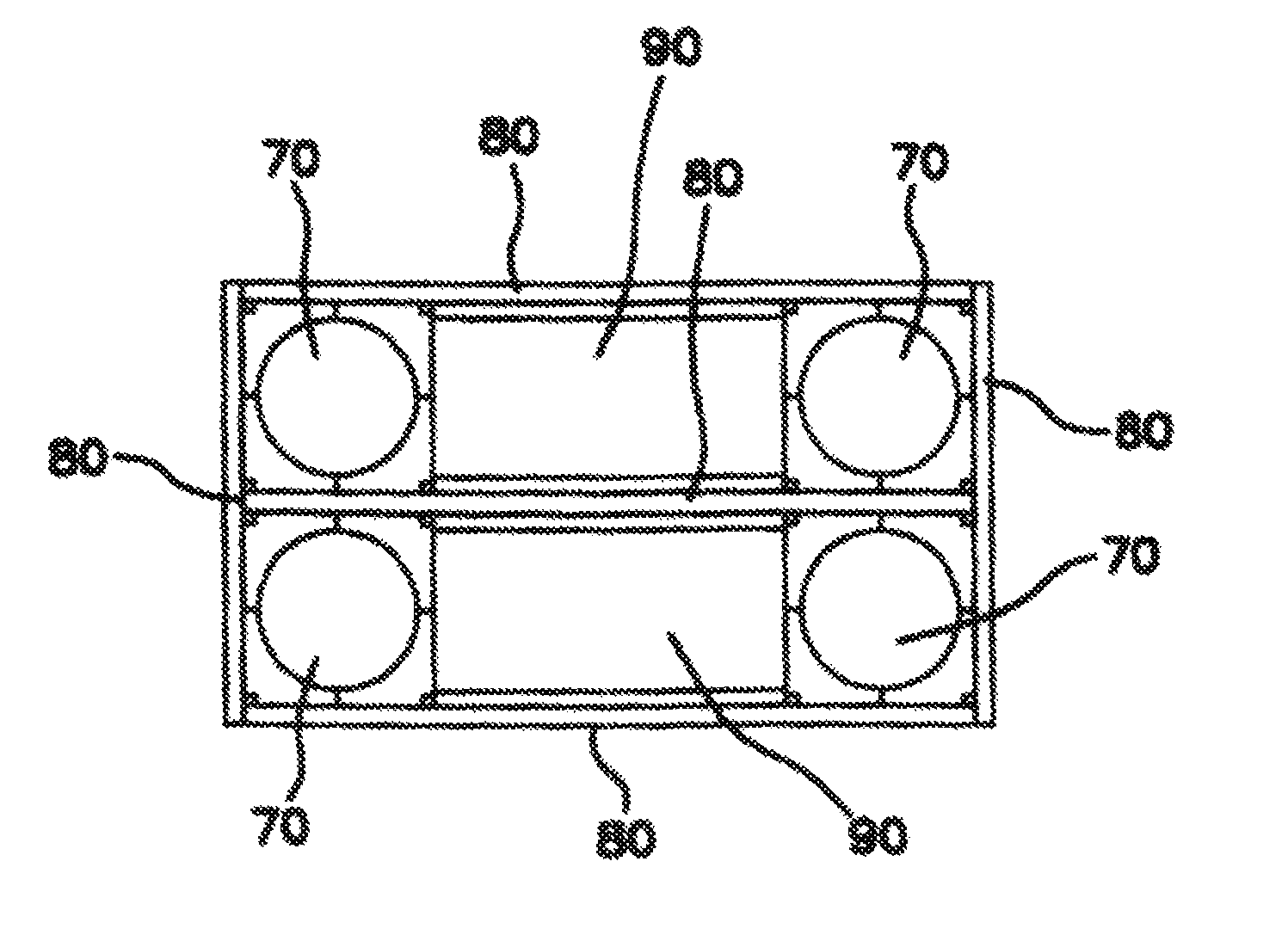
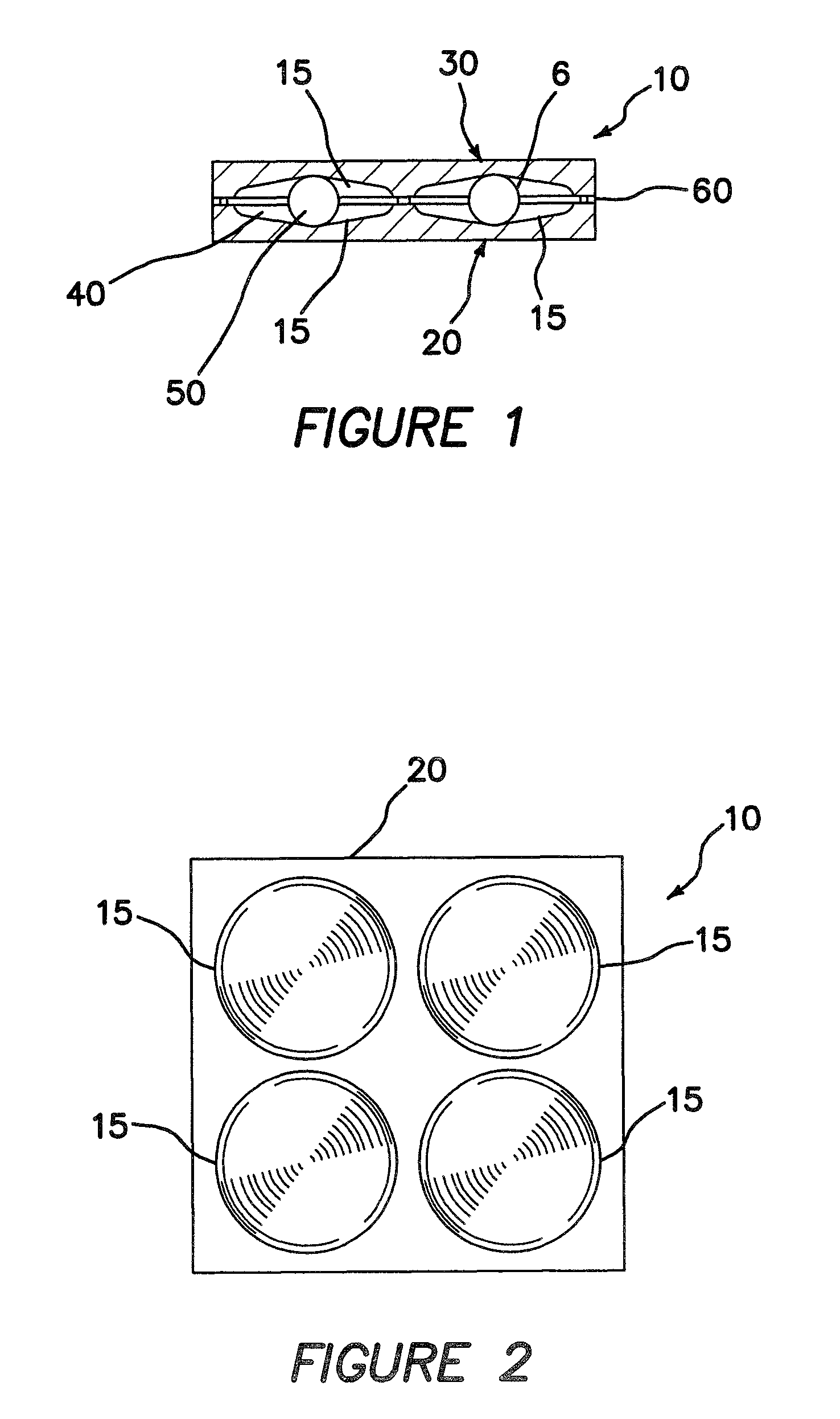
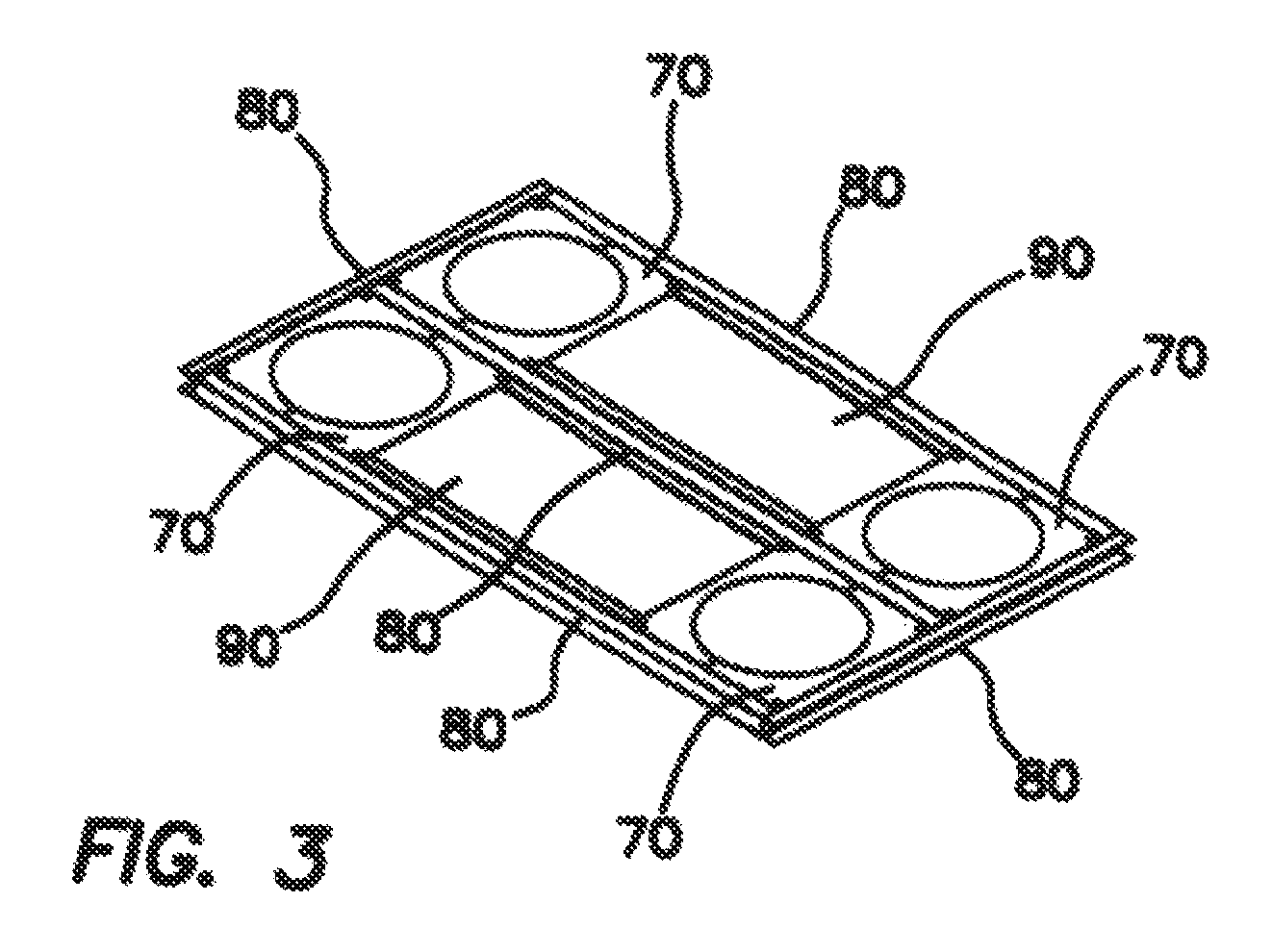
[0032]In accordance with various exemplary embodiments of the present invention, an isolation platform 10 is provided to filter vibrations and reduce noise in devices supported by platform 10. Preliminarily, it should be appreciated by one skilled in the art, that the following description is of exemplary embodiments only and is not intended to limit the scope, applicability, or configuration of the invention in any way. Rather, the following description merely provides convenient illustrations for implementing various embodiments of the invention. For example, various changes may be made in the design and arrangement of the elements described in the exemplary embodiments herein without departing from the scope of the invention as set forth in the appended claims.

[0033]That being said, generally, platform 10 comprises a lower plate 20 which is mounted to the foundation upon which the structure is intended to be supported. A second, oppositely disposed (upper) plate 30 is disposed ab...


PUM


Abstract

The present invention provides a platform for supporting various equipment and / or structure which assists in isolating such structure from vibrations (“noise”) external to the platform. Generally, the platform comprises upper and lower plates, having conical depressions, upon which the upper plate supports the above-mentioned structure, and the lower plate contacting surface / area upon which the supported structure otherwise would have rested. Between the upper and lower plates, a plurality of rigid, spherical bearings are placed within the conical depressions, thereby allowing the upper and lower plates to displace relative to one another. Additionally, the platform may be provided with retaining mechanisms for holding the structure to be supported, maintaining the plates together and providing additional damping effects.

Description

FIELD OF THE INVENTION[0001]The present invention relates, generally, to isolation platforms for use in supporting various structures, and, more particularly, to platforms which isolate the structures they are supporting from ambient vibrations, generally external to the platform.BACKGROUND OF THE INVENTION[0002]Isolation bearings of the type used with bridges, buildings, machines, and other structures potentially subject to seismic phenomena are typically configured to support a bearing load, i.e., the weight of the structure being supported. In this regard, it is desirable that a particular seismic isolation bearing be configured to support a prescribed maximum vertical gravity loading at every lateral displacement position.[0003]The conservative character of a seismic isolation bearing may be described in terms of the bearing's ability to restore displacement caused by seismic activity or other external applied forces. In this regard, a rubber bearing body, leaf spring, coil spri...

Claims


Application Information

Patent Timeline
Patent Type & Authority Patents(United States)
IPC IPC(8): E04B1/98F16M7/00E04H9/02F16F15/04
CPCE04H9/023E04H9/02E04H9/021E04H9/0235
Inventor KEMENY, ZOLTAN A.
Owner WORKSAFE TECHNOLOGY INC
Learn More