Slidable spring-loaded transition-to-turbine seal apparatus and heat-shielding system, comprising the seal, at transition/turbine junction of a gas turbine engine

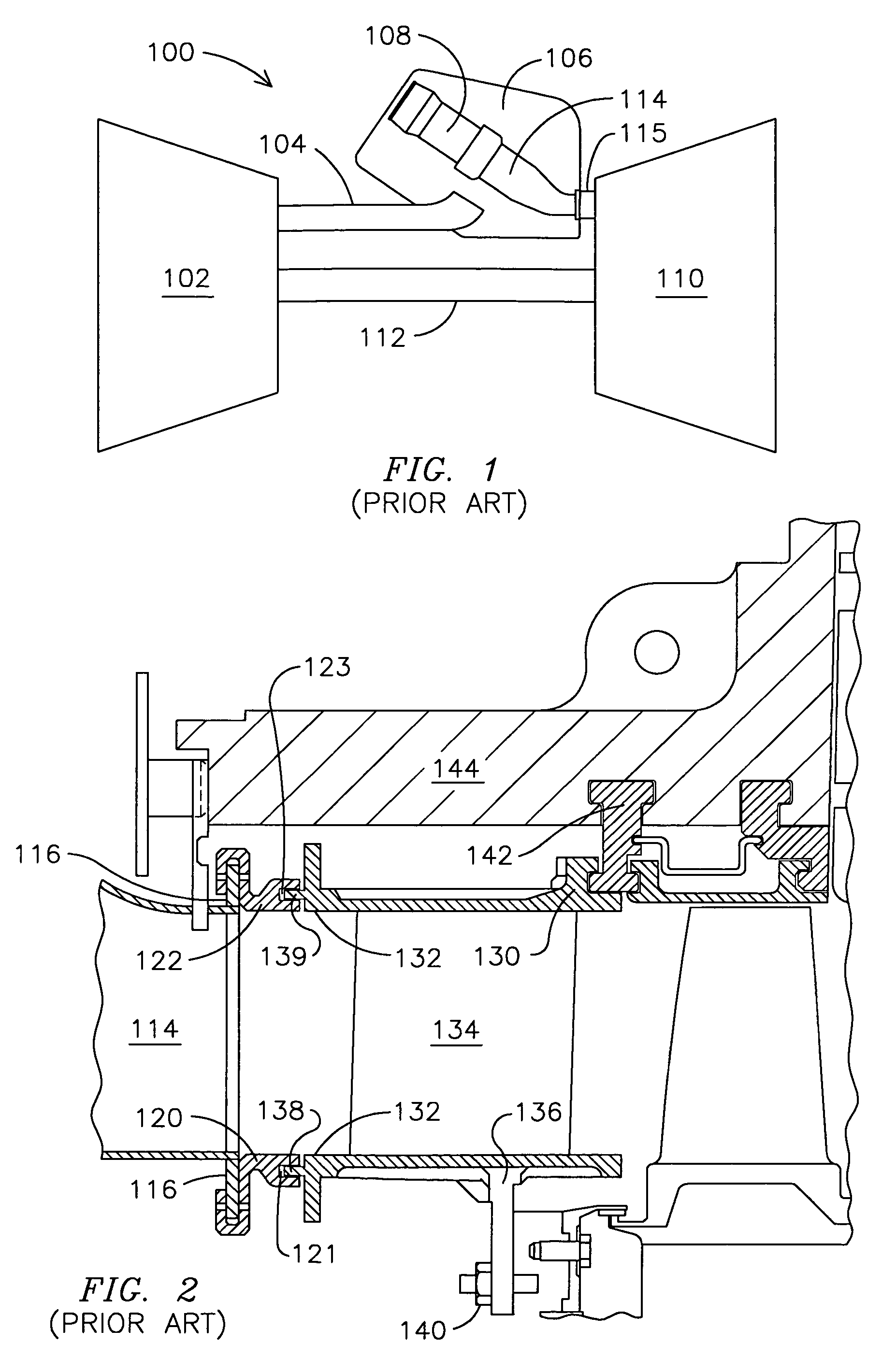
a gas turbine engine and transition/turbine junction technology, applied in the field of seals, can solve the problems of large gaps, air loss, and type seals not being retained over the life of components

Active Publication Date: 2010-08-31
SIEMENS ENERGY INC
View PDF25 Cites 47 Cited by
  • Summary
  • Abstract
  • Description
  • Claims
  • Application Information

AI Technical Summary

Problems solved by technology

Consequently, the design of such seal has presented a challenge that resulted in various approaches that attempt to find a suitable balance between seal cost, reliability, durability, installation and repair ease, performance, and effect on adjacent components.
Further, regarding wear and overall performance, it is appreciated that the initial close tolerances of newly installed “floating” type seals are not retained over the component life.
Wear results in larger gaps, through which compressed air enters the hot gas path.
Such air loss is expected to reduce performance efficiency and increase No, emissions.
Also, for turbine designs that utilize a plurality of row 1 vane segments per transition, the independent movement of adjacent row 1 vane segments increases the dynamic challenges placed on a transition-to-turbine seal for such configuration.

Method used


Image

  • Slidable spring-loaded transition-to-turbine seal apparatus and heat-shielding system, comprising the seal, at transition/turbine junction of a gas turbine engine
  • Slidable spring-loaded transition-to-turbine seal apparatus and heat-shielding system, comprising the seal, at transition/turbine junction of a gas turbine engine
  • Slidable spring-loaded transition-to-turbine seal apparatus and heat-shielding system, comprising the seal, at transition/turbine junction of a gas turbine engine

Examples


Embodiment Construction

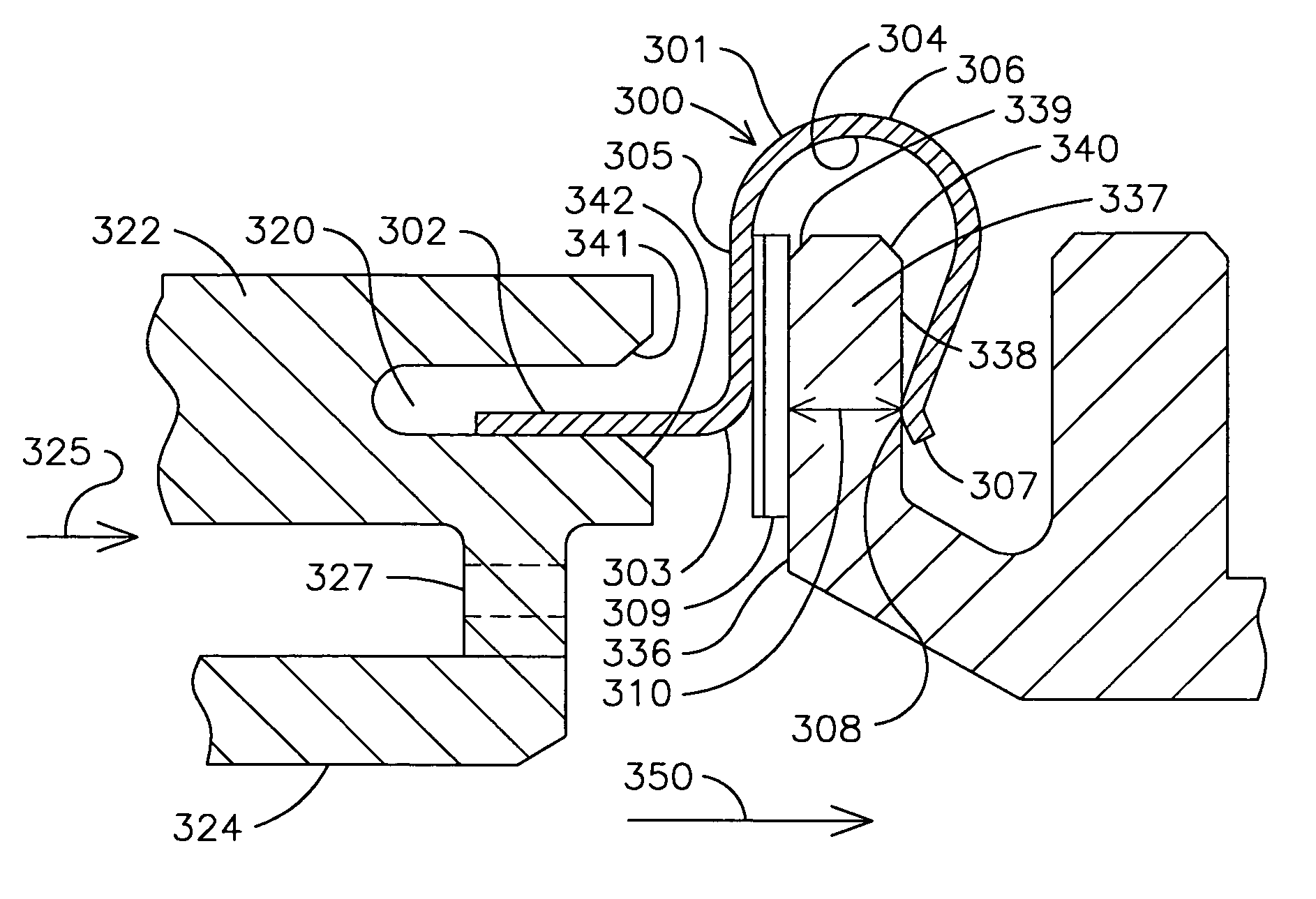
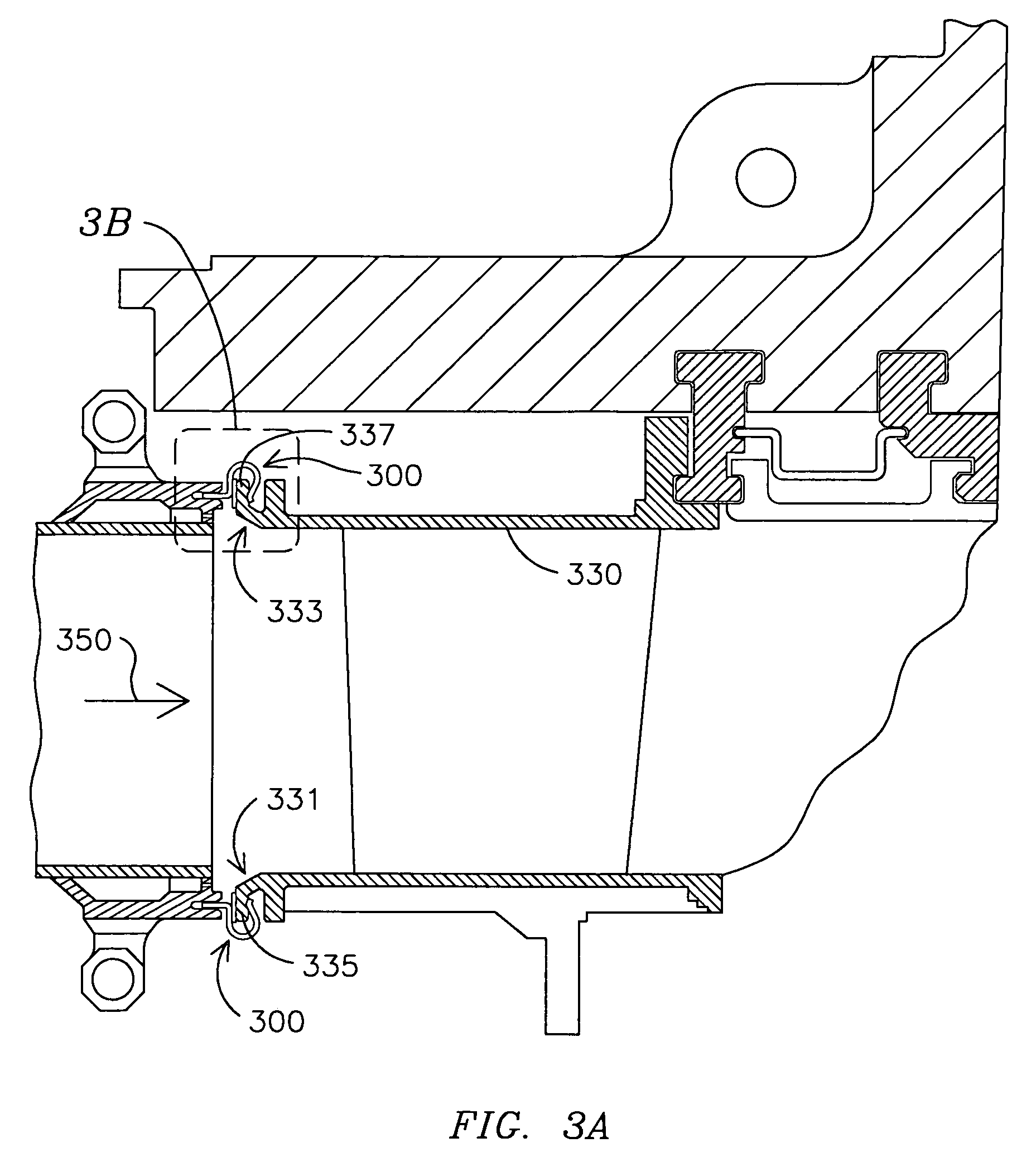
[0016]A transition-to-turbine interface comprising a spring-loaded member for insertion over a row 1 vane segment flange could, it was hypothesized, substantially reduce air losses through the seal, and reduce wear on the relatively expensive row 1 vane segments by permitting relatively unencumbered sawtoothing motion. A spring-loaded seal was conceptualized as a solution to the multiple design and performance challenges of a transition-to-turbine seal. Initial trials of a spring-loaded seal, however, resulted in unacceptable, catastrophic component failure.

[0017]Thereafter, it was realized that, despite such initial failure, a spring-loaded transition-to-turbine seal could endure under turbine operating conditions if it could be removed from or isolated from the flow path of hot, combusted gases. After such problem identification and realization of an approach to a solution, embodiments of a spring-loaded transition-to-turbine seal, and a system that comprises such seal, were devel...


PUM


Abstract

One embodiment of a transition-to-turbine seal (300) comprises a first, flattened section (302) adapted to be received in a peripheral axial slot (320) of a transition (325), and a second, generally C-shaped section (301). The generally C-shaped section (301) comprises a flattened portion (305) near the first, flattened section (302), and a curved portion (306) extending to a free edge (307). A fiber metal strip component (309) may be attached to the flattened portion (305) to define a first engagement surface adapted to engage an upstream side (336) of an outer vane seal rail (337), and a second engagement surface 308, adjacent the free edge (307), provides an opposed wear surface adapted to engage a downstream side (338) of the outer vane seal rail (337). System embodiments also are described, in which such transition-to-turbine seal (300) is isolated from a hot gas path (350) by provision of a plurality of cooling apertures (327) in the transition (325).

Description

FIELD OF INVENTION[0001]The invention generally relates to a gas turbine engine, and more particularly to a seal between a transition and a turbine of such engine.BACKGROUND OF THE INVENTION[0002]In gas turbine engines, air is compressed at an initial stage, then is heated in combustion chambers, and the hot gas so produced passes to a turbine that, driven by the hot gas, does work which may include rotating the air compressor.[0003]In a typical industrial gas turbine engine a number of combustion chambers combust fuel and hot gas flowing from these combustion chambers is passed via respective transitions (also referred to by some in the field as ducts or transition pieces) to respective entrances of the turbine. More specifically, a plurality of combustion chambers commonly are arranged radially about a longitudinal axis of the gas turbine engine, and likewise radially arranged transitions respectively comprise outlet ends that converge to form an annular inflow of hot gas to the t...

Claims


Application Information

Patent Timeline
Patent Type & Authority Patents(United States)
IPC IPC(8): F04D29/04F23R3/42
CPCF01D9/023F01D11/005F02C7/28
Inventor WEAVER, ADAM J.NORDLUND, RAYMOND S.ALLEN, DAVID B.DAVIES, DANIEL O.
Owner SIEMENS ENERGY INC
Why Eureka
Try Eureka