Optimization of hydrocarbon injection during diesel particulate filter (DPF) regeneration

a technology of diesel particulate filter and hydrocarbon injection, which is applied in the direction of engines, machines/engines, mechanical equipment, etc., can solve the problem that the threshold temperature does not accurately indicate whether a hydrocarbon fuel is presen

Inactive Publication Date: 2010-08-31
GM GLOBAL TECH OPERATIONS LLC
View PDF4 Cites 4 Cited by
  • Summary
  • Abstract
  • Description
  • Claims
  • Application Information

AI Technical Summary

Benefits of technology

The present invention provides a diesel engine system with an exhaust system that includes a catalyst and a diesel particulate filter. The system includes a first module that determines the light-off temperature of the catalyst based on the exhaust flow rate and a second module that selectively generates an enable signal based on the light-off temperature and the catalyst temperature. The DPF regeneration sequence is enabled based on the enable signal. The second module generates the enable signal when the catalyst temperature is greater than the light-off temperature. The EFR is determined based on the mass air flow and the fueling rate of the engine. The light-off temperature is determined based on the space velocity of the catalyst and the space velocity is determined based on the EFR. The second module maintains the enable signal when the catalyst temperature is less than the light-off temperature and is greater than the catalyst lower limit temperature. The technical effect of this invention is to improve the performance and efficiency of diesel engines by optimizing the catalyst light-off temperature and the DPF regeneration sequence based on the exhaust flow rate and the catalyst temperature.

Problems solved by technology

However, the exhaust temperature achieving a threshold temperature does not accurately indicate whether a hydrocarbon fuel can be combusted within the exhaust under all operating conditions.

Method used


Image

  • Optimization of hydrocarbon injection during diesel particulate filter (DPF) regeneration
  • Optimization of hydrocarbon injection during diesel particulate filter (DPF) regeneration
  • Optimization of hydrocarbon injection during diesel particulate filter (DPF) regeneration

Examples


Embodiment Construction

[0017]The following description of the preferred embodiment is merely exemplary in nature and is in no way intended to limit the invention, its application, or uses. For purposes of clarity, the same reference numbers will be used in the drawings to identify similar elements. As used herein, the term module refers to an application specific integrated circuit (ASIC), an electronic circuit, a processor (shared, dedicated, or group) and memory that execute one or more software or firmware programs, a combinational logic circuit, or other suitable components that provide the described functionality.

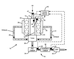
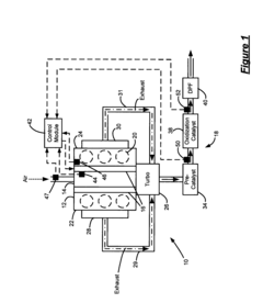
[0018]Referring now to FIG. 1, an exemplary diesel engine system 10 is schematically illustrated. It is appreciated that the engine system 10 is merely exemplary in nature and that the DPF regeneration control of the present invention can be implemented in various engine systems. The diesel engine system 10 includes a diesel engine 12, an intake manifold 14, a common rail fuel injection syst...


PUM


Abstract

A diesel engine system having an exhaust system with a catalyst and a diesel particulate filter includes a first module that determines a light-off temperature of the catalyst based on an exhaust flow rate (EFR) through the exhaust system and a second module that selectively generates an enable signal based on the light-off temperature and a catalyst temperature. A DPF regeneration sequence is enabled based on said enable signal.

Description

CROSS-REFERENCE TO RELATED APPLICATION[0001]This application claims the benefit of U.S. Provisional Application No. 60 / 661,536, filed on Mar. 14, 2005. The disclosure of the above application is incorporated herein by reference.FIELD OF THE INVENTION[0002]The present invention relates to diesel engines, and more particularly to diesel particulate filter (DPF) regeneration.BACKGROUND OF THE INVENTION[0003]Diesel engines have higher efficiency than gasoline engines due to the increased compression ratio of the diesel combustion process and the higher energy density of diesel fuel. As a result, a diesel engine provides improved gas mileage than an equivalently sized gasoline engine.[0004]The diesel combustion cycle produces particulates that are typically filtered from the exhaust gases. A diesel particulate filter (DPF) is usually disposed along the exhaust stream to filter the diesel particulates from the exhaust. Over time, however, the DPF becomes full and must be regenerated to re...

Claims


Application Information

Patent Timeline
Patent Type & AuthorityPatents(United States)
IPC IPC(8): F01N3/00
CPCF01N3/023F01N3/035
InventorMARLETT, CHAD E.MITAL, RAHUL
OwnerGM GLOBAL TECH OPERATIONS LLC