
System and method for controlling an air conditioner or heat pump

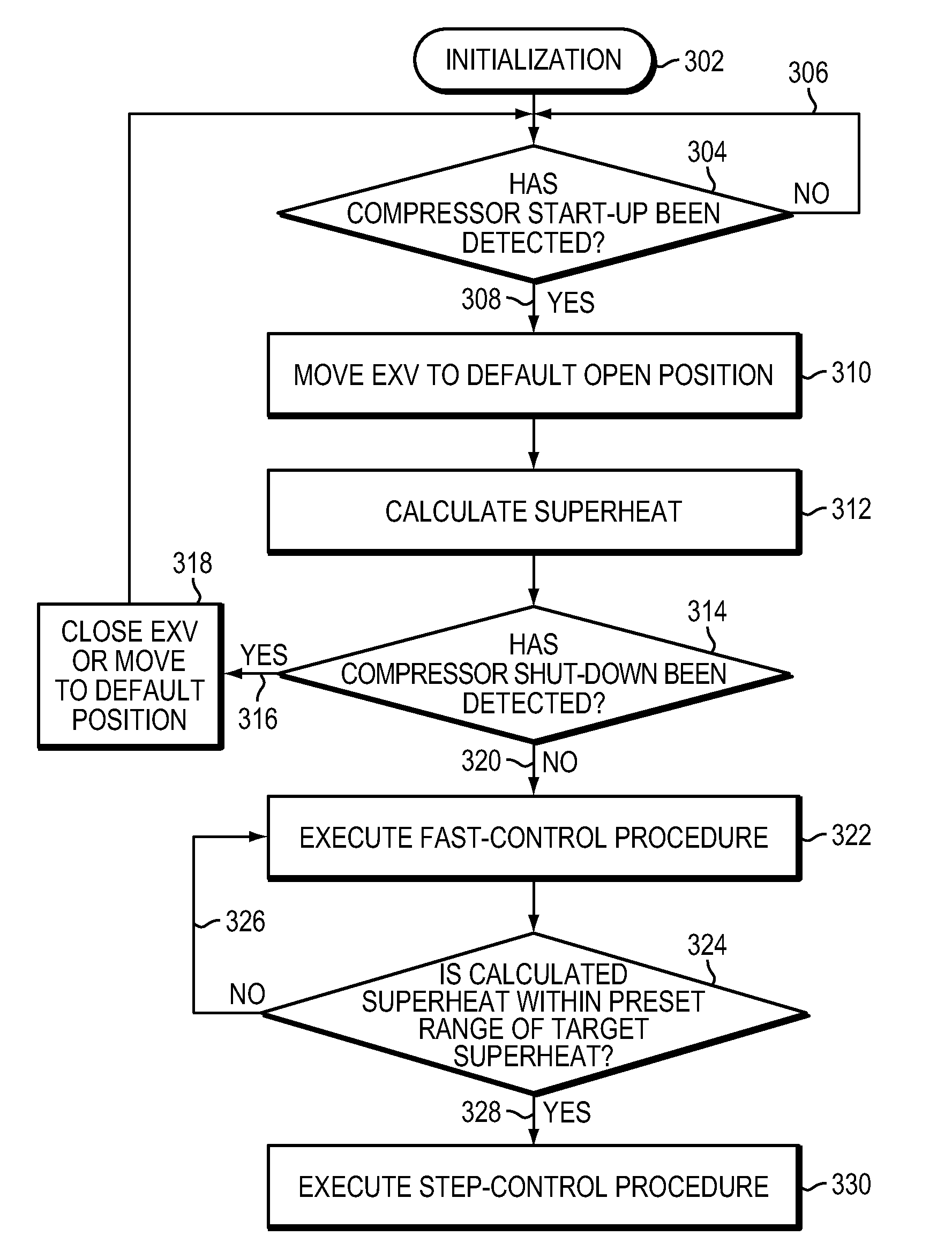
a technology for controlling systems and heat pumps, applied in process and machine control, lighting and heating apparatus, instruments, etc., can solve problems such as shortening valve life, affecting so as to improve the efficiency of air conditioning systems, prolong the life of compressors, and avoid compressor damage.

Active Publication Date: 2010-08-31
NORTEK GLOBAL HVAC
View PDF38 Cites 16 Cited by
  • Summary
  • Abstract
  • Description
  • Claims
  • Application Information

AI Technical Summary

Benefits of technology

"The invention is a control procedure for air conditioning or heat pump systems that uses an electronic expansion valve (EXV) and an EXV controller to measure the condition of the refrigerant upstream of the compressor and adjust the EXV accordingly to prevent damage to the compressor and improve system efficiency. The control procedure ensures that the refrigerant exiting the evaporator is at a desired superheat level, minimizing the degree of opening and closing of the EXV and improving cooling capacity and performance. The invention also provides a method for accurately measuring the refrigerant's superheat level by using pressure measurements and compensating for pressure drop along the refrigerant path."

Problems solved by technology

Otherwise, liquid refrigerant may enter the compressor causing damage to the compressor, as liquid is largely incompressible.
Prior art EXV implementations generally maintain an appropriate flow of superheated gaseous refrigerant to the compressor during steady state operation, but such EXVs typically do not react quickly to transient states.
This shortens valve life.

Method used


Image

  • System and method for controlling an air conditioner or heat pump
  • System and method for controlling an air conditioner or heat pump
  • System and method for controlling an air conditioner or heat pump

Examples


second embodiment

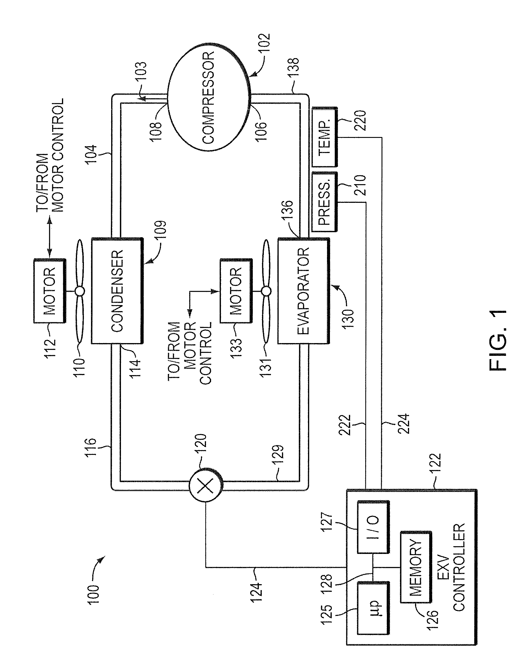
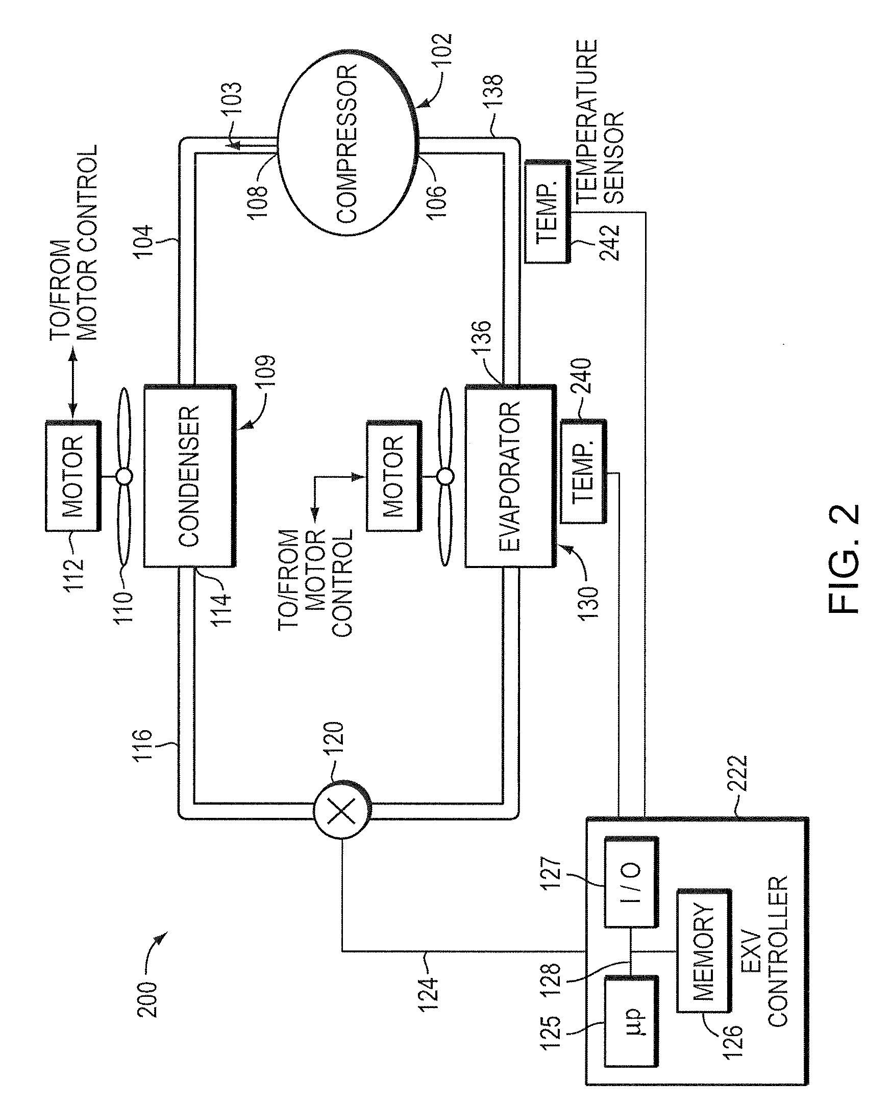
[0029]FIG. 2 illustrates an air conditioning system 200 according to the present invention. The air-conditioning system 200 includes components that are similar or identical to those described with reference to FIG. 1 above. Such like components have been similarly numbered, e.g., compressor 102, condenser 109, EXV 120, evaporator 130 and blowers 110, 131. According to the embodiment of FIG. 2, the desired gaseous state at the compressor inlet 106 is attained by controlling the EXV 120 to move between open and closed positions in response to readings of the prevailing temperature of the refrigerant by a first temperature sensor 240 provided in communication with the fluid flow through the evaporator 130, and a second temperature sensor 242 provided in communication with the fluid flow at the outlet 136 of the evaporator. An EXV controller 222 receives temperature readings from the temperature sensors 240, 242. The EXV controller 222 preferably uses these temperature readings to calc...

third embodiment

[0069]FIG. 6 illustrates an air conditioning system 600 according to the present invention. The air-conditioning system 600 includes components that are similar or identical to those described with reference to FIGS. 1 and 2 above. Such like components have been similarly numbered, e.g., compressor 102, condenser 109, EXV 120, evaporator 130 and blowers 110, 131. According to the embodiment of FIG. 6, the desired gaseous state at the compressor inlet 106 is attained by controlling the EXV 120 to move between open and closed positions in response to a reading of outdoor air temperature by an outdoor temperature sensor 602. An EXV controller 604 receives temperature readings from the temperature sensor 602. The memory 126 of the EXV controller 604 preferably stores one or more look-up tables, such as table 800, which is described in more detail below. The EXV controller 604 preferably uses the outdoor temperature reading to control the EXV 120. In this embodiment, the EXV controller 6...


PUM


Abstract

A control procedure operates an expansion valve of an air conditioning system. The control procedure utilizes a first control procedure to bring a calculated superheat value within a range of a target superheat value, and a second control procedure to cause the calculated superheat value to match the target superheat value. Both the first and second control procedures preferably use Proportional, Integral, Derivative control algorithms.

Description

BACKGROUND OF THE INVENTION[0001]1. Field of the Invention[0002]This invention relates to heating and cooling systems and, more specifically, to controlling heating and cooling systems.[0003]2. Background Information[0004]An air conditioner typically has at least four major components. Those components are a compressor, a condenser, a throttling device (such as a fixed orifice, a thermal expansion valve, or an electronic expansion valve), and an evaporator.[0005]During normal operation, the compressor pumps the refrigerant from a low-pressure, low-temperature vapor state to a high-pressure, high-temperature vapor state. The hot refrigerant gas passes through the condenser, which is generally located outside in communication with ambient air. The condenser rejects heat to the ambient air typically though the use of an electric fan. The refrigerant leaving the condenser is normally in a sub-cooled liquid state. The liquid refrigerant then flows though the throttling device with a sign...

Claims


Application Information

Patent Timeline
Patent Type & Authority Patents(United States)
IPC IPC(8): F25B41/04
CPCF25B41/062F25B2600/21F25B41/34Y02B30/70
Inventor CHEN, YICHEN, JIEREIFEL, ALLAN J.KOESTERER, DAVID L.
Owner NORTEK GLOBAL HVAC
Learn More