Surgical stapling instrument having load sensing control circuitry

a control circuit and load-sensing technology, applied in the field of surgical stapler instruments, can solve the problems of narrowness and longness of instruments used in such procedures, and achieve the effect of enhancing the operation of surgical instruments

Active Publication Date: 2010-08-31
CILAG GMBH INT
View PDF207 Cites 1862 Cited by
  • Summary
  • Abstract
  • Description
  • Claims
  • Application Information

AI Technical Summary

Benefits of technology

[0009]The invention overcomes the above-noted and other deficiencies of the prior art by providing a surgical instrument that incorporates an electrical pressure sensor positioned to receive a compressive load when the surgical instrument is actuated. Control circuitry that monitors the electrical pressure sensor then generates a control signal responsive to that sensed compressive load to enhance operation of the surgical instrument.
[0010]In one aspect of the invention, a surgical instrument has a staple applying assembly with first and second opposing compression surfaces that clamp tissue to be stapled and imparts a compressive force thereby to a pressure transducer. The staple applying assembly is closed by a handle portion and actuated by a firing member moved by the handle portion through a shaft. Control circuitry responds to the sensed compression load of the staple applying assembly to send a control signal to an electrical actuator. Thereby, a desired sequence of events may be enforced that are dependent upon first successfully clamping a desired amount of tissue, avoiding dry firing of an actuator in the absence of sufficient tissue or ineffective activation of the actuator in the presence of too much tissue.

Problems solved by technology

Moreover, laparoscopic and endoscopic procedures often require the surgeon to act on organs, tissues and / or vessels far removed from the incision.
Thus, instruments used in such procedures are typically long and narrow while being functionally controllable from a proximal end of the instrument.

Method used


Image

  • Surgical stapling instrument having load sensing control circuitry
  • Surgical stapling instrument having load sensing control circuitry
  • Surgical stapling instrument having load sensing control circuitry

Examples


Embodiment Construction

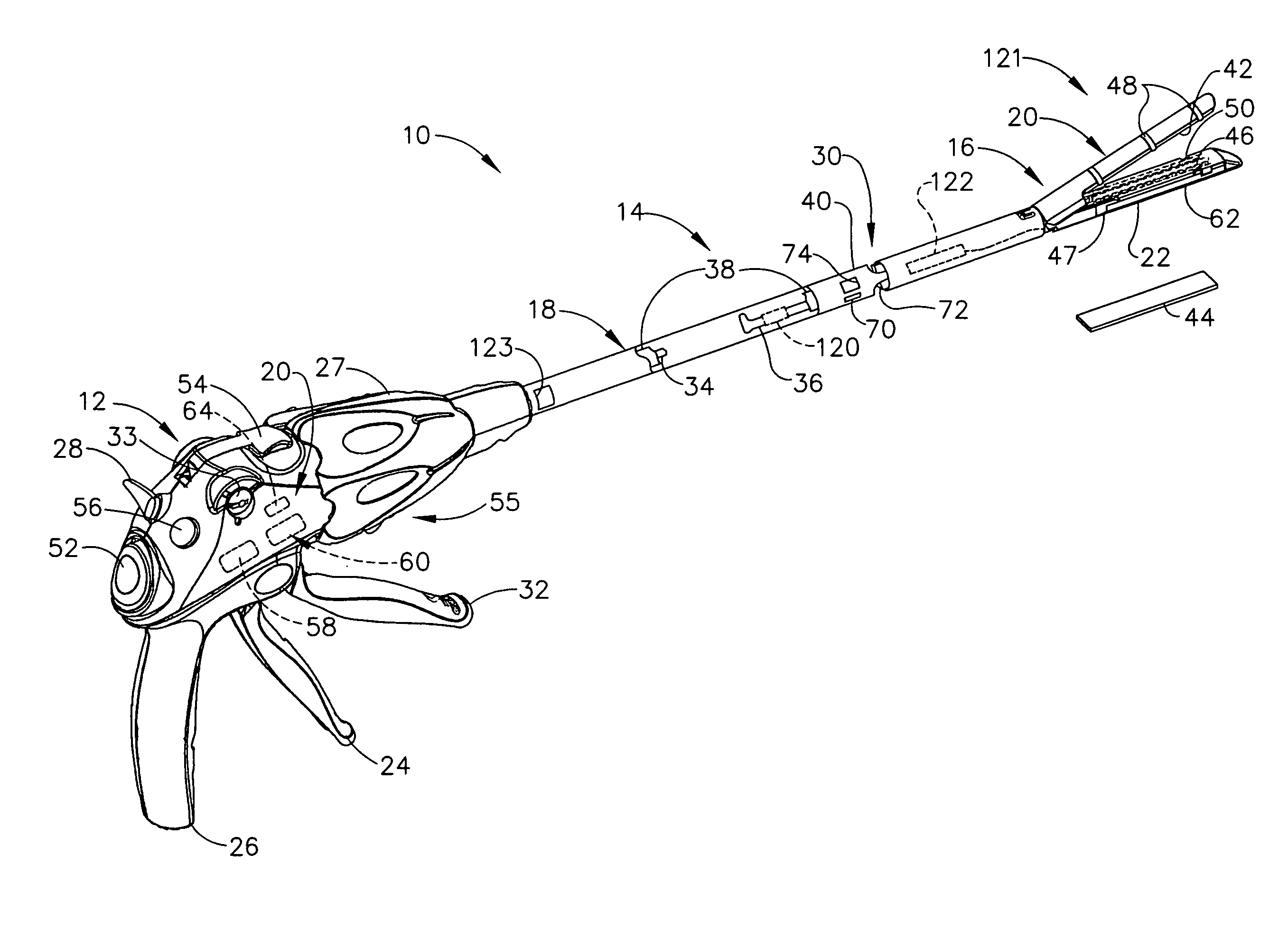
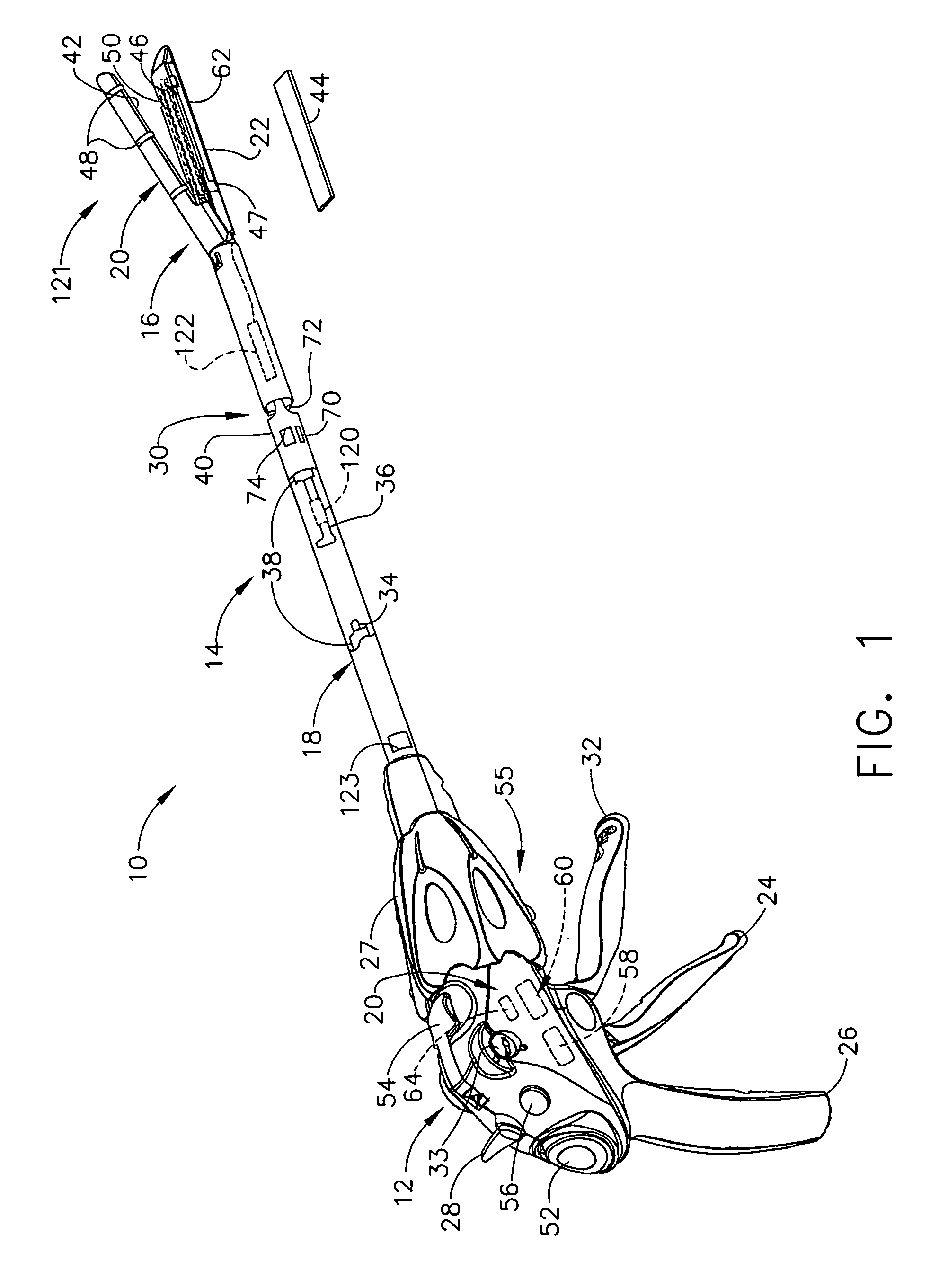
[0028]Turning to the Drawings, wherein like numerals denote like components throughout the several views, in FIG. 1, a surgical stapling and severing instrument 10 includes a handle portion 12 that manipulates to position an implement portion 14 formed from a fastening end effector, specifically a staple applying assembly 16, distally attached to an elongate shaft 18. The implement portion 14 is sized for insertion through a cannula of a trocar (not shown) for an endoscopic or laparoscopic surgical procedure with an upper jaw (anvil) 20 and a lower jaw 22 of the staple applying assembly 16 closed by depression of a closure trigger 24 toward a pistol grip 26 of the handle portion 12.

[0029]Once inserted into an insufflated body cavity or lumen, the surgeon may rotate the implement portion 14 about its longitudinal axis by twisting a shaft rotation knob 27 that engages across a distal end of the handle 12 and a proximal end of the elongate shaft 18. The surgeon may selectively move to ...


PUM

PropertyMeasurementUnit
voltage potentialaaaaaaaaaa
thresholdaaaaaaaaaa
compressiveaaaaaaaaaa

Abstract

A surgical instrument for being endoscopically or laparoscopically inserted into a surgical site for simultaneous stapling and severing of tissue includes load sensing pressure transducers strategically placed for closed loop control and monitoring. Load sensing within a staple applying assembly (end effector) may provide feedback for preventing firing with insufficient or too much tissue, or to sense appropriate presence buttress material, to deploy buttress material after firing is sensed.

Description

CROSS REFERENCE TO RELATED APPLICATIONS[0001]This application is a Continuation in Part of U.S. patent application Ser. No. 11 / 082,495, entitled “Surgical Instrument Incorporating an Electrically Acutated Articulation Mechanism”, filed on Mar. 17, 2005, the disclosure of which is hereby incorporated by reference in its entirety.FIELD OF THE INVENTION[0002]The present invention relates in general to surgical stapler instruments that are capable of applying lines of staples to tissue while cutting the tissue between those staple lines and, more particularly, to improvements relating to stapler instruments and improvements in processes for forming various components of such stapler instruments including adding bolstering material to the severed and stapled tissue.BACKGROUND OF THE INVENTION[0003]Endoscopic and laparoscopic surgical instruments are often preferred over traditional open surgical devices since a smaller incision tends to reduce the post-operative recovery time and complic...

Claims


Application Information

Patent Timeline
Patent Type & Authority Patents(United States)
IPC IPC(8): A61B17/068
CPCA61B17/072A61B17/07207A61B17/07292A61B2017/00022A61B2019/4836A61B2017/07214A61B2019/464A61B2019/465A61B2017/00115A61B2090/064A61B2090/065A61B2090/0807
Inventor SHELTON, IV, FREDERICK E.
Owner CILAG GMBH INT
Why Eureka
Try Eureka