
Forward discharge blower unit

a blower unit and forward discharge technology, applied in the field of blower trucks, can solve the problems of limiting mechanical design, limiting mechanical design, and likely too heavy rear end to allow maximization of material containment, so as to facilitate the loading of material at the rear end, limit mechanical design, and maximize the effect of weigh

Active Publication Date: 2010-08-31
ASTEC INDS
View PDF16 Cites 3 Cited by
  • Summary
  • Abstract
  • Description
  • Claims
  • Application Information

AI Technical Summary

Benefits of technology

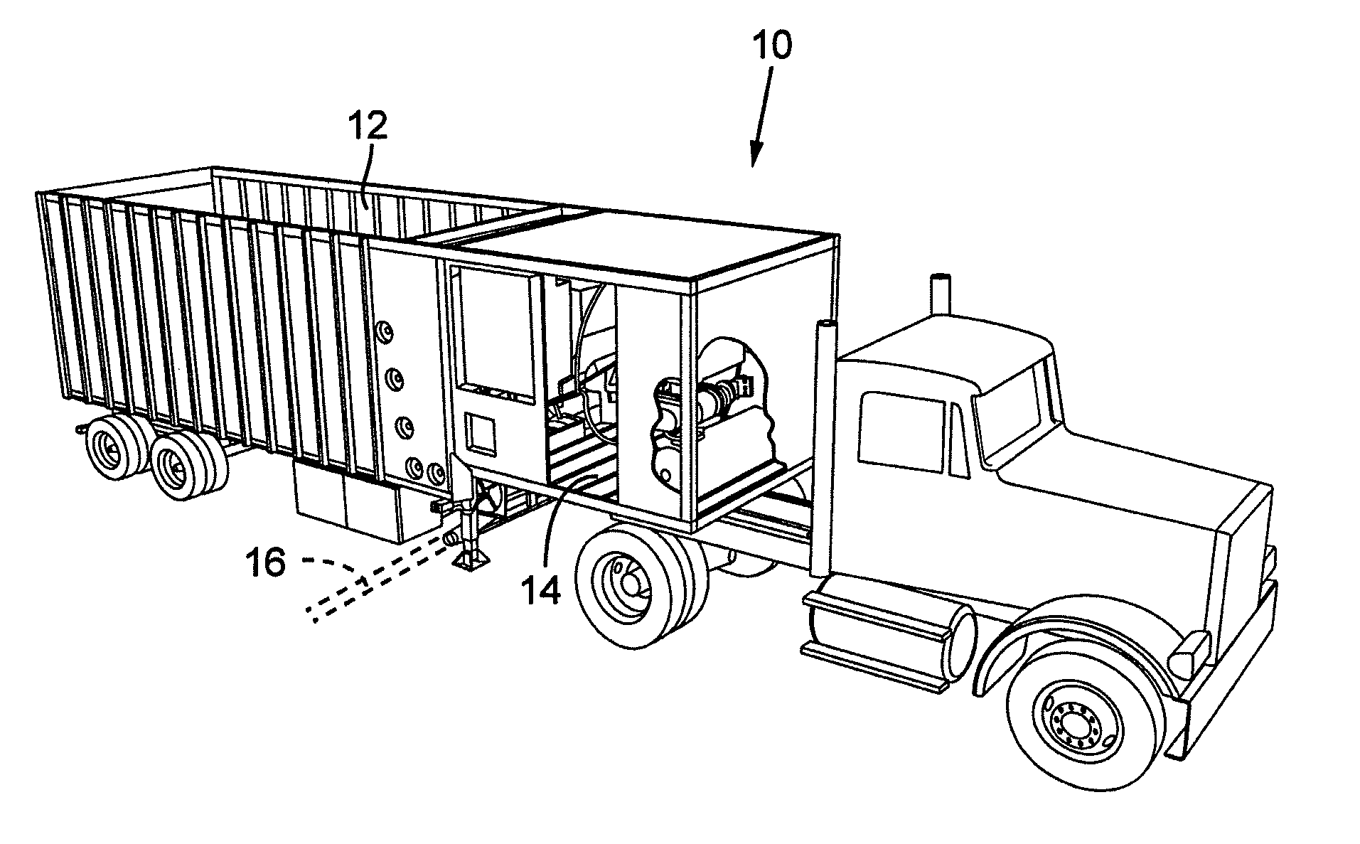
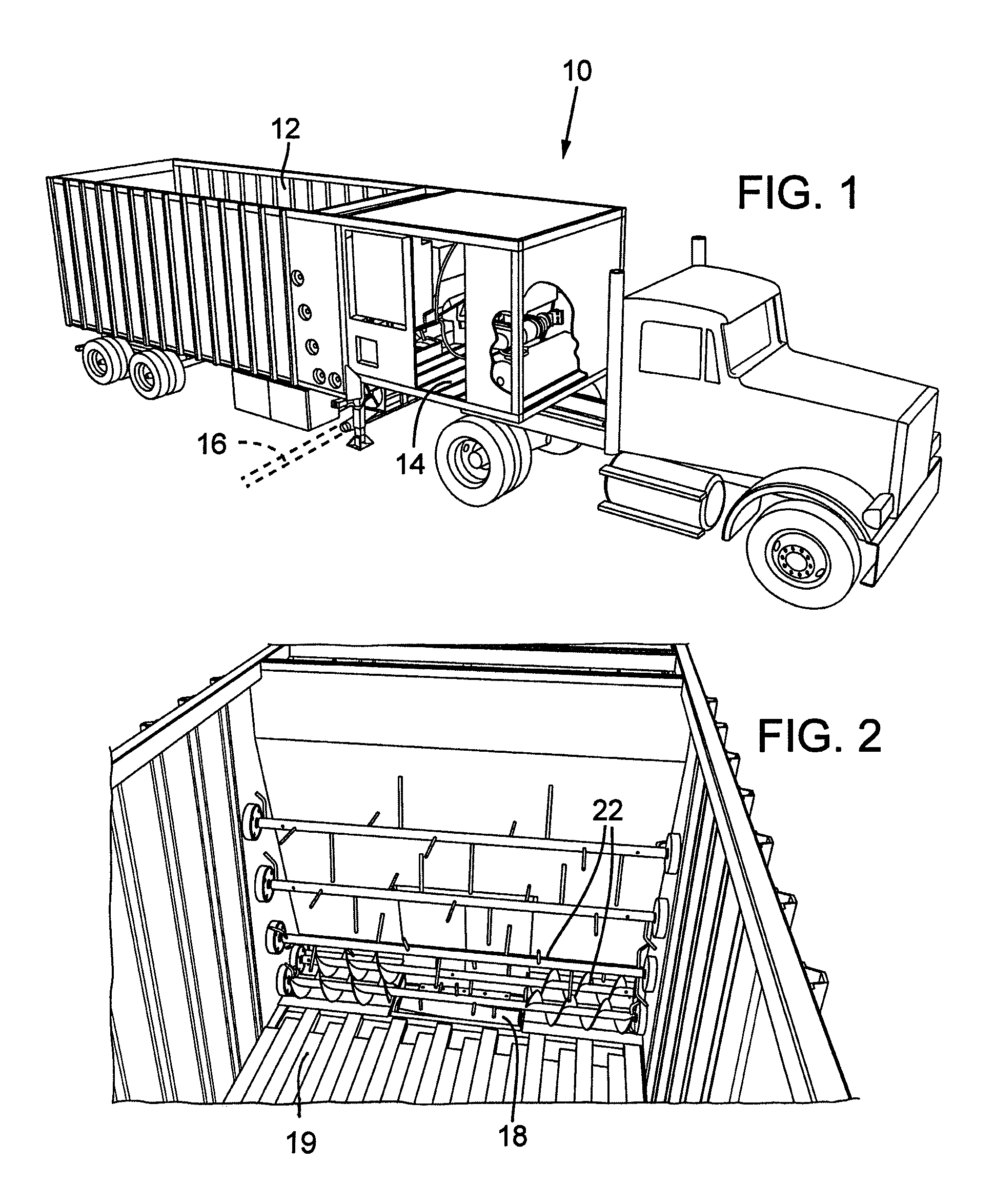
[0004]The blower unit as generally described has a number of deficiencies to which the present invention is directed. With the material metering mechanism including air lock feeder, auger / tines, air / material mixing chamber, hose connections and the like, located at the rear end of the blower unit, there is first, a weight distribution issue. The rear end will likely be too heavy to allow maximization of material containment. By locating the mentioned equipment e.g. over the front end axles, the rear end axle's weight can be maximized with the weight of the material to be dispersed.
[0005]Whereas loading and unloading of material may be accomplished through an open top of the container, it frequently is desirable to also or instead of top loading, to provide loading through a tail endgate. Placement of the equipment at the front end with material feed directed toward the front end from the rear end, in accordance with embodiments of the present invention, allows for more convenient rear end loading of the material.
[0007]In occurrences where a job is completed prior to fully emptying of the container, the unloading of the unused material through a tail endgate or rear door is inhibited by the material metering mechanism located at the rear end. In accordance with embodiments of the present invention a blower unit having a front end location and including a reversible live floor, the material can be readily moved rearwardly and dispersed through the tail endgate.
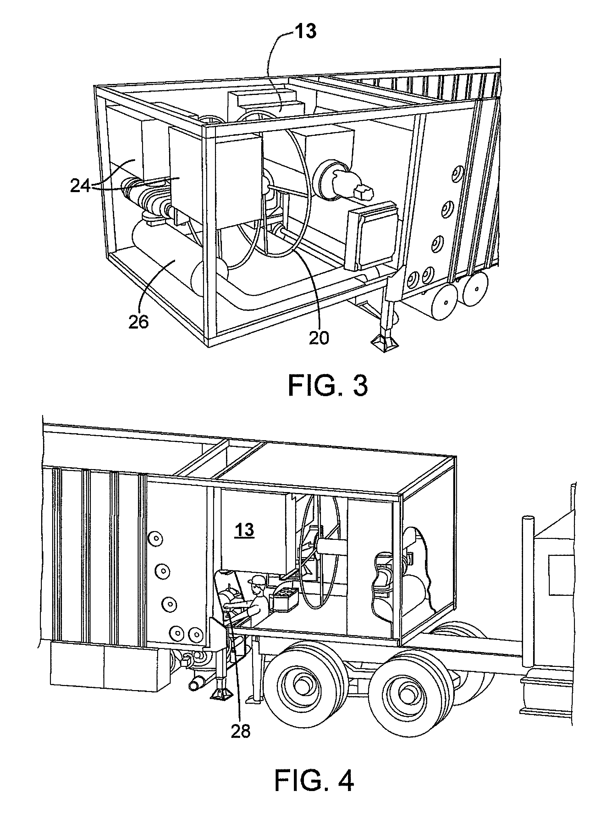
[0008]Still further, the container having front end location for the material metering mechanism in accordance with various embodiments may be more readily adapted for the loading and transporting of other items e.g. as may be desirable for use at a work site. Also the servicing of the material metering mechanism may be readily accommodated via an access doorway provided at a front end location of the container. These and other advantages will become apparent to those skilled in the art upon reference to the following detailed description having reference to the accompanying drawings of the invention.

Problems solved by technology

With the material metering mechanism including air lock feeder, auger / tines, air / material mixing chamber, hose connections and the like, located at the rear end of the blower unit, there is first, a weight distribution issue.
The rear end will likely be too heavy to allow maximization of material containment.
This requires complex mechanism and limits mechanical design, and creates mechanical design difficulties that are avoided with the material metering mechanism mounted on the front end.

Method used


Image

  • Forward discharge blower unit
  • Forward discharge blower unit
  • Forward discharge blower unit

Examples


Embodiment Construction

[0014]In the following detailed description, reference is made to the accompanying drawings which form a part hereof and in which is shown by way of illustration embodiments in which the invention may be practiced. It is to be understood that other embodiments may be utilized and structural or logical changes may be made without departing from the scope of the present invention. Therefore, the following detailed description is not to be taken in a limiting sense, and the scope of embodiments in accordance with the present invention is defined by the appended claims and their equivalents.

[0015]Various operations may be described as multiple discrete operations in turn, in a manner that may be helpful in understanding embodiments of the present invention; however, the order of description should not be construed to imply that these operations are order dependent.

[0016]The description may use perspective-based descriptions such as up / down, back / front, and top / bottom. Such descriptions ...


PUM


Abstract

A blower unit is configured to have a forward containment portion for housing mechanical equipment for receiving and dispensing material particles as ground cover. A rear containment portion is provided for containing such material particles. A material mover preferably operable in forward and rearward direction will feed material to the mechanical equipment for breakdown and pneumatic disbursement. A rear door design enables convenient unloading of the material with the live floor directionally reversed. Benefits include a more convenient means for servicing of the blower mechanism including e.g. an engine providing a motor source, dispensing hose, rotary air lock feeder and mixing chamber e.g. T injector or dropout (term as used in the industry).

Description

RELATED APPLICATION[0001]This application claims priority to U.S. Provisional Application No. 60 / 712,982, entitled “FORWARD DISCHARGE BLOWER UNIT” filed on Aug. 30, 2005, which is hereby fully incorporated by reference.FIELD OF INVENTION[0002]The present invention relates generally to the field of blower trucks, and specifically to a blower truck having a discharge of container contents at the forward end of the container.BACKGROUND[0003]Blower trucks are often used to transport and blow (pneumatically convey) into place bark dust, mulch, compost, wood chips, rubber particles, and other fragmented materials. The blower truck and these materials are commonly used, but not exclusively, for landscaping, erosion control, mud control, new or regenerative lawn installations, and / or animal bedding. Current blower unit configurations include elongate box-like material containers that are mounted to a truck or trailer. They may consist of a large material container that contains a conveying ...

Claims


Application Information

Patent Timeline
Patent Type & Authority Patents(United States)
IPC IPC(8): B60P1/38
CPCB60P1/60
Inventor BANDSTRA, JOHN R.
Owner ASTEC INDS
Learn More