Method and device for determining a takeoff trajectory allowing to maximize the takeoff weight of an aircraft

a technology of aircraft takeoff and trajectory, applied in the direction of process and machine control, instruments, navigation instruments, etc., can solve the problems of aircraft not being able to stop on the remaining runway length, assuming a significant and expensive human involvement, and not taking into account, so as to maximize the takeoff weight of the aircraft

Active Publication Date: 2014-02-25
AIRBUS OPERATIONS (SAS)
View PDF10 Cites 1 Cited by
  • Summary
  • Abstract
  • Description
  • Claims
  • Application Information

AI Technical Summary

Benefits of technology

[0029]The present invention further relates to a device for determining at least one auxiliary takeoff trajectory of an aircraft for maximizing the takeoff weight of the aircraft.

Problems solved by technology

On the other hand, when an engine breakdown occurs while the speed of the aircraft is equal to or higher than such a decision speed, the aircraft is no longer able to stop on the remaining runway length and should therefore continue the takeoff.
This is a laborious task requiring the interactive use of several specific softwares and could take up to one week of work for a specialized team.
Despite the use of softwares, such a usual method thus supposes a significant and expensive human involvement.
In addition, such a known method does not take into consideration, for determining the auxiliary takeoff trajectory, a possible engine breakdown occurring at a speed of the aircraft higher than the decision speed.
Since the turn radius is an increasing function of the aircraft speed and a decreasing function of the rolling angle of the aircraft, the follow-up of the piloting instructions for the nominal auxiliary takeoff (that is, established for an engine breakdown occurring at the decision speed), for which turns are taken at constant rolling, for example at 15 degrees, results in more significant turn radii than for a breakdown at the decision speed.
Too late an engine breakdown could therefore result in an effective auxiliary takeoff trajectory, the ground track of which substantially differs from that of the nominal auxiliary takeoff trajectory, that could create collision risks with obstacles, more particular in a mountain area.
Furthermore, if an auxiliary takeoff trajectory has been found allowing for the takeoff of the aircraft at a high maximum weight, it is not ensured that the aircraft will be able to fly over, with such a high maximum weight, obstacles on the standard takeoff trajectory with all its engines in operation, and all the more with an engine breakdown occurring after the divergence point.

Method used


Image

  • Method and device for determining a takeoff trajectory allowing to maximize the takeoff weight of an aircraft
  • Method and device for determining a takeoff trajectory allowing to maximize the takeoff weight of an aircraft
  • Method and device for determining a takeoff trajectory allowing to maximize the takeoff weight of an aircraft

Examples


Embodiment Construction

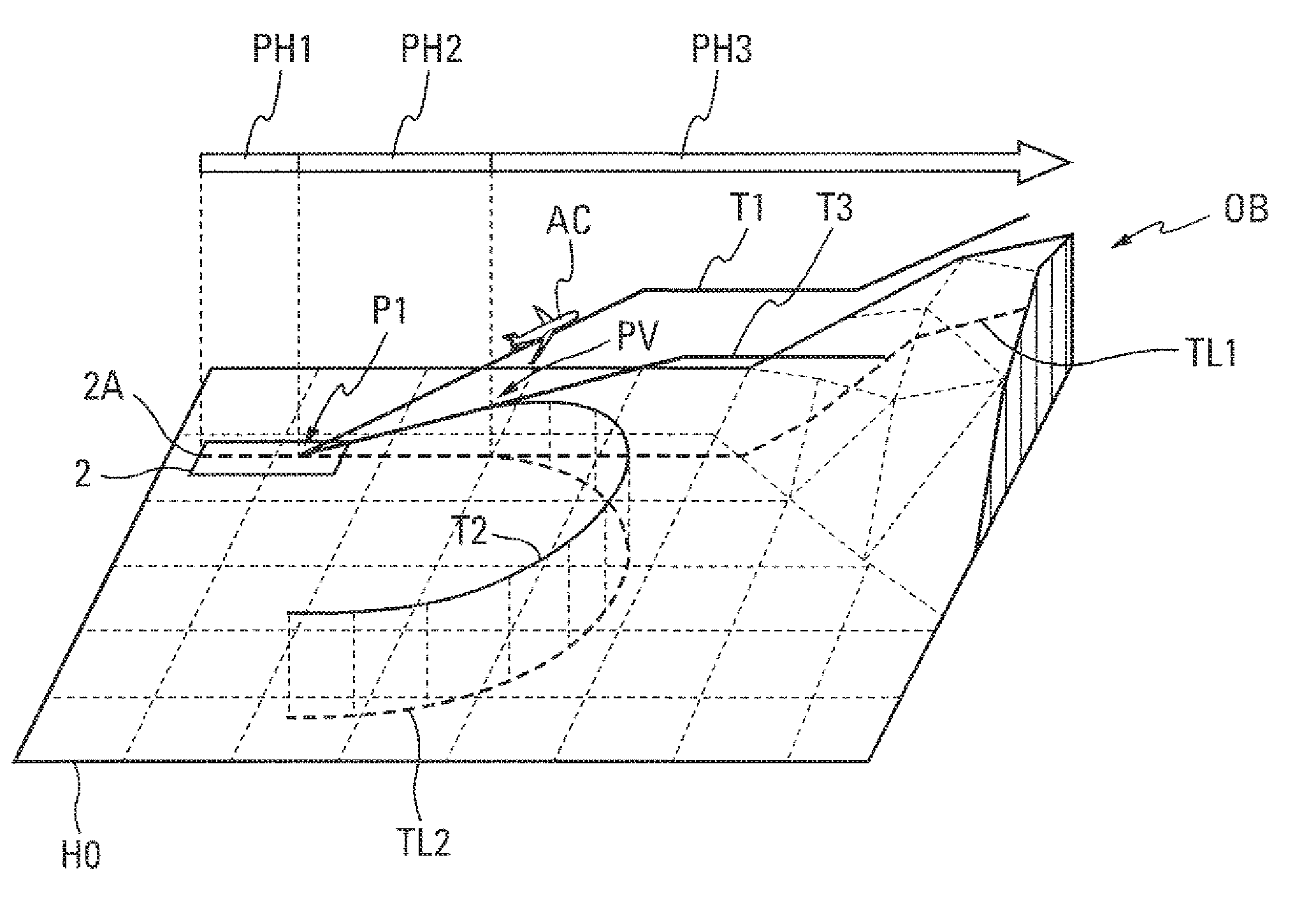
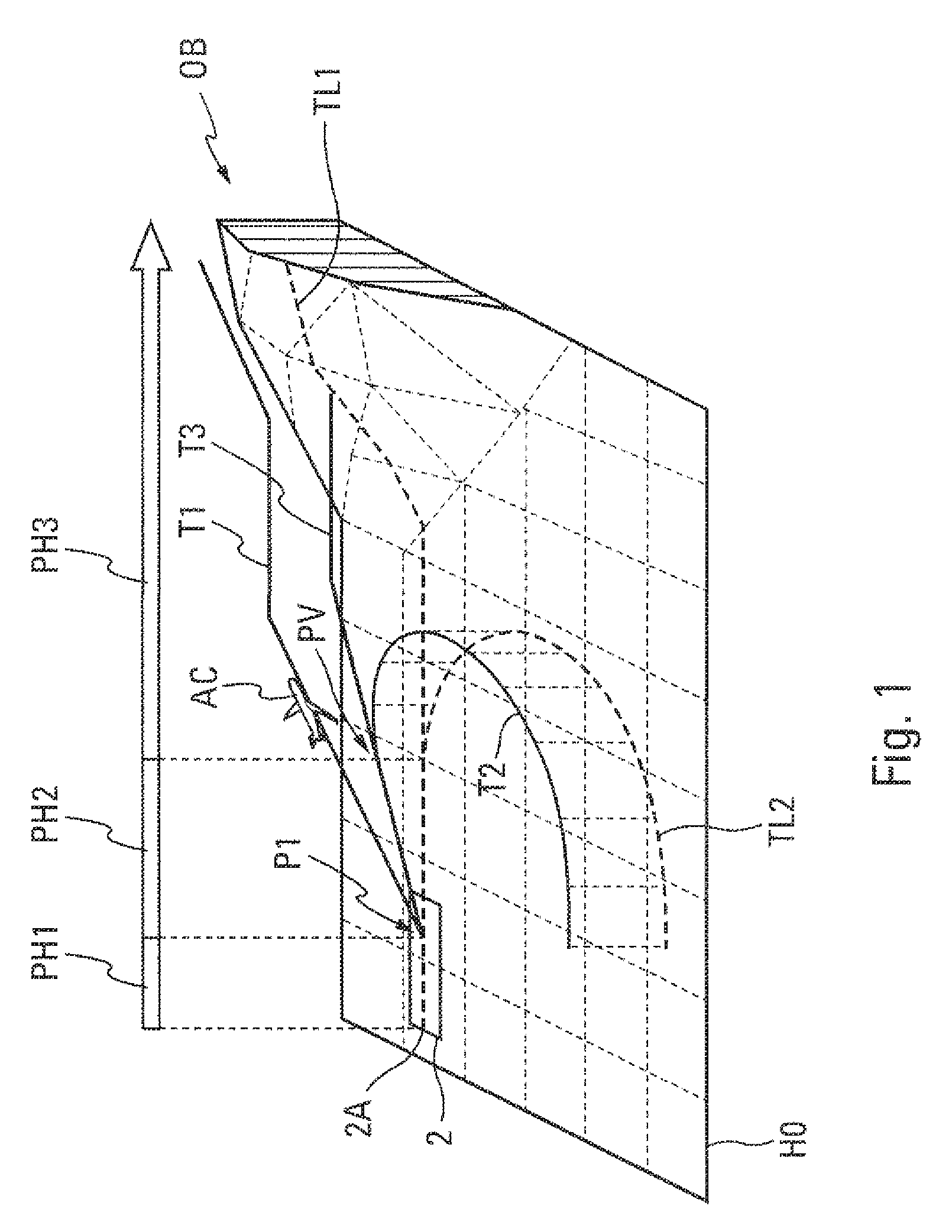
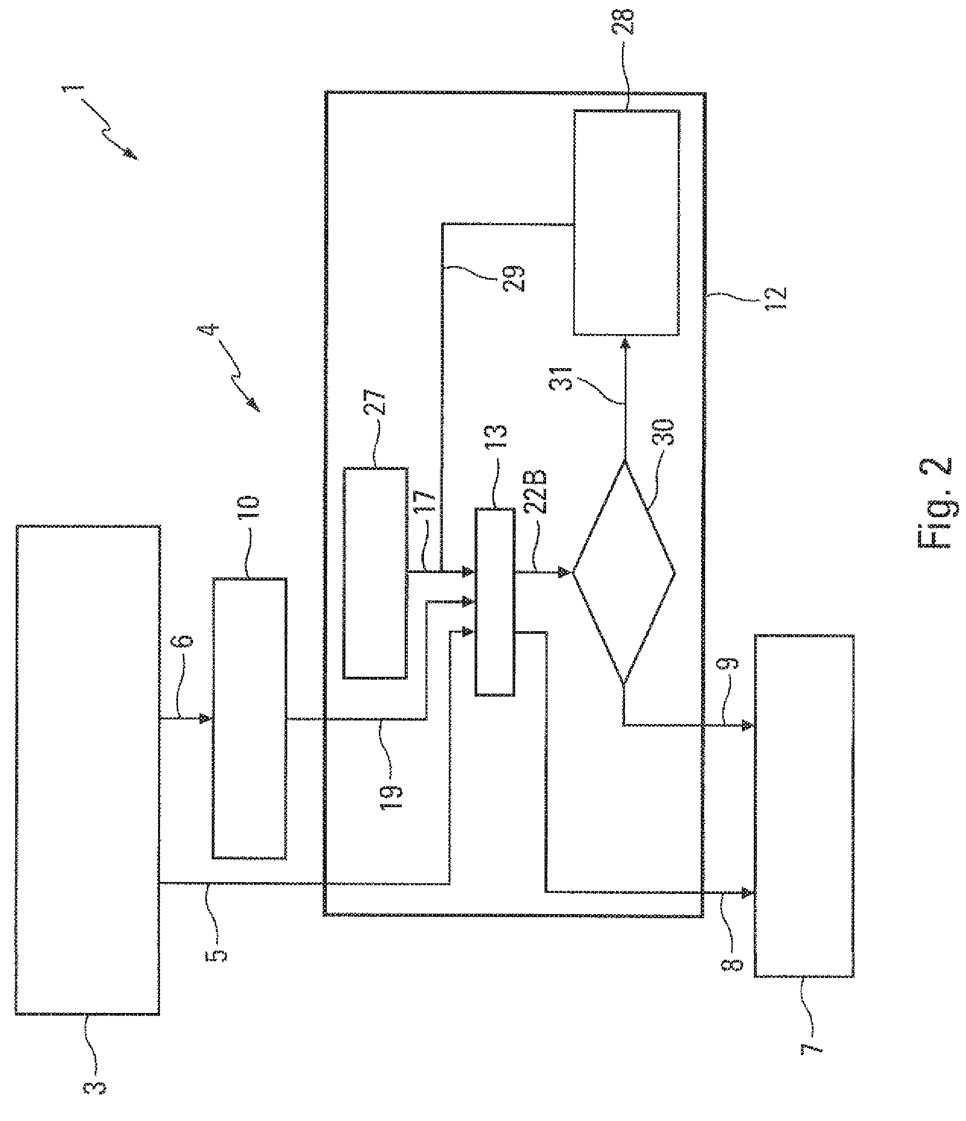
[0039]The trajectory analysis device 1 according to this invention and schematically shown in FIG. 2 is provided for determining at least one takeoff trajectory of an aircraft, in particular of a transport aircraft AC. FIG. 1 schematically illustrates the takeoff of an aircraft AC being carried out from a takeoff runway 2, in the vicinity of which obstacles OB are present, in the present case, a mountain or a high hill. Generally, the takeoff of the aircraft AC is carried out following a standard takeoff trajectory T1, the lateral profile TL1 of which (representing the vertical projection of the trajectory T1 on the ground comprising a horizontal plane HO) is rectilinear and extends according to the axis 2A of the runway 2 to be used for the takeoff. Such a standard takeoff trajectory T1 is commonly referred to using the English acronym SID, for >. In order to save the aircraft AC from having to fly over obstacles OB, an auxiliary takeoff trajectory T2 is also determined (commonly r...


PUM


Abstract

A trajectory analysis device automatically determines an auxiliary takeoff trajectory including a curvilinear lateral profile, which allows to maximize the takeoff weight of the aircraft. To this end, the device includes an initial data generation device, an auxiliary takeoff trajectory determination device, and a display device. The crew of the aircraft may then review the optimized auxiliary takeoff trajectory.

Description

TECHNICAL FIELD[0001]The present invention relates to a method and a device for determining a takeoff trajectory of an aircraft for maximizing the takeoff weight of the aircraft, in particular of a transport airplane.BACKGROUND[0002]It is known that the takeoff of aircrafts should meet safety requirements being defined by the air regulation. In particular, when an engine breakdown occurs upon the takeoff of an aircraft, it is necessary to make sure that flying over obstacles such as mountains, antennas, trees or buildings, being located in the vicinity of the takeoff runway along the trajectory followed by the aircraft, remains possible, and this, with a sufficient safety margin.[0003]Such a constraint could require the crew to limit the maximum takeoff weight of the aircraft, so as to allow the latter to generate a climbing slope sufficient for avoiding the obstacles.[0004]In order to reduce the extent of such a constraint on the value of the maximum weight, an auxiliary takeoff tr...

Claims


Application Information

Patent Timeline
Patent Type & Authority Patents(United States)
IPC IPC(8): G06F19/00
CPCG05D1/0661
Inventor LAPORTE, SERGETALGORN, BASTIEN
Owner AIRBUS OPERATIONS (SAS)
Why Eureka
Try Eureka