Exerciser having magnets adjusting device

a technology of adjusting device and exerciser, which is applied in the direction of cardiovascular exercise device, gymnastic exercise, sport apparatus, etc., can solve the problems of reducing the adjusting range of resistance, increasing production cost, inaccurate calculation of resistance and damage of components, etc., to enhance the convenience and stability of manipulation, improve durability, and move smoothly

Inactive Publication Date: 2010-08-31
LO CHIU HSIANG
View PDF11 Cites 44 Cited by
  • Summary
  • Abstract
  • Description
  • Claims
  • Application Information

AI Technical Summary

Benefits of technology

[0008]The first objective of the present invention is to provide an exerciser with an improved magnets adjusting device which makes magnetic units linearly and smoothly move along the radial of a flywheel, in order to enhance the convenience and stability of manipulation in terms of the variation of resistance damping and, on the other hand, to improve the durability by avoiding the damage of components. The technique to achieve above objective of the present invention applies a magnets adjusting device which includes a linearly extended guiding rail, a sliding unit and

Problems solved by technology

1. The mechanism of certain prior arts includes a slider with a U-shaped horizontal cross-section. There is a set of magnetic units on each side of the slider, and each set of the magnetic units is facing toward both sides of a flywheel. In order to avoid the inner surface of the slider contacting with the edge of the flywheel, either the moving range of the magnet units, corresponding to the flywheel, must be narrowed that it causes a disadvantage of reducing the adjusting range of resistance, or the size of the slider must be increased that it causes another disadvantage of increasing the producti

Method used


Image

  • Exerciser having magnets adjusting device
  • Exerciser having magnets adjusting device
  • Exerciser having magnets adjusting device

Examples


Embodiment Construction

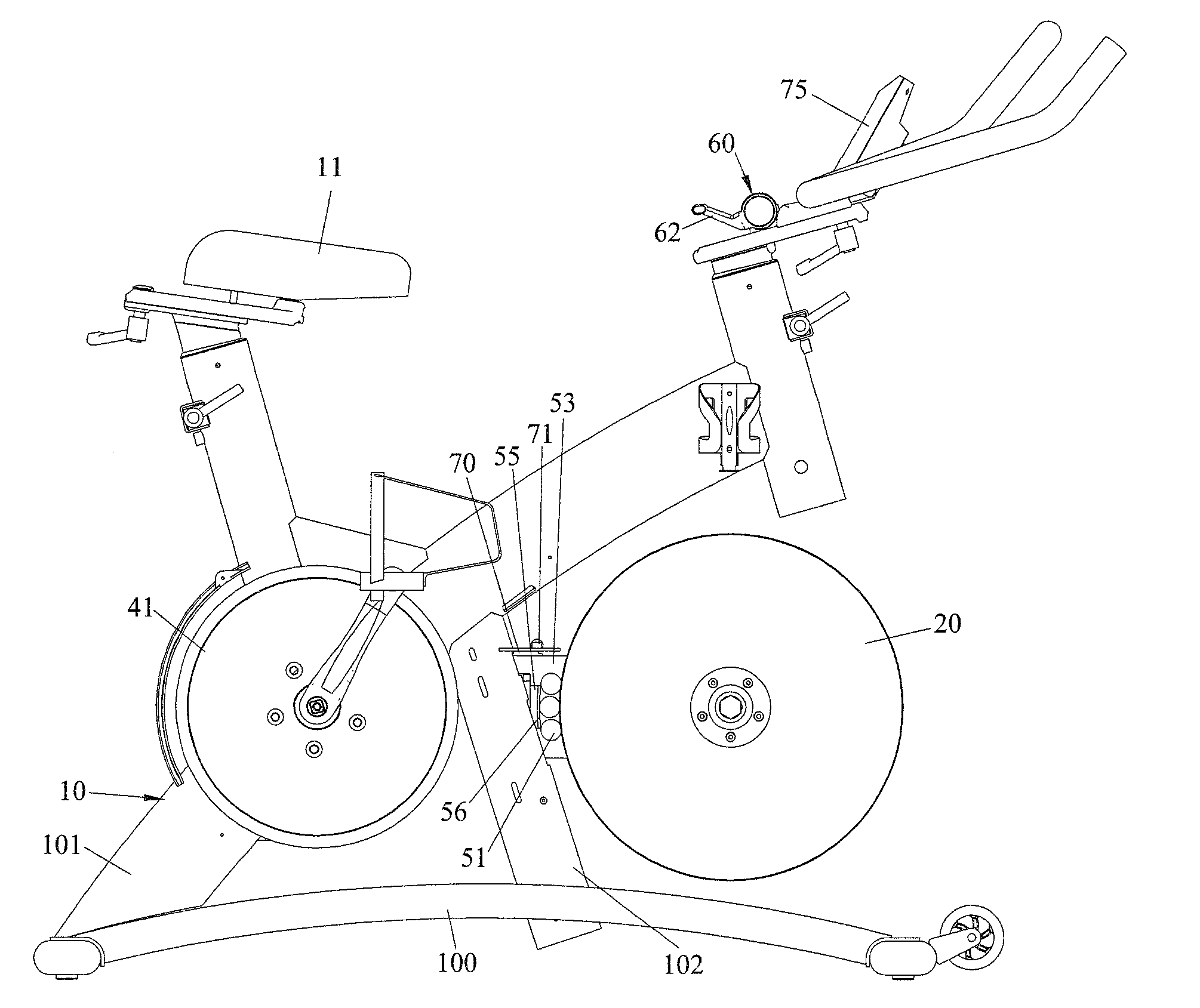
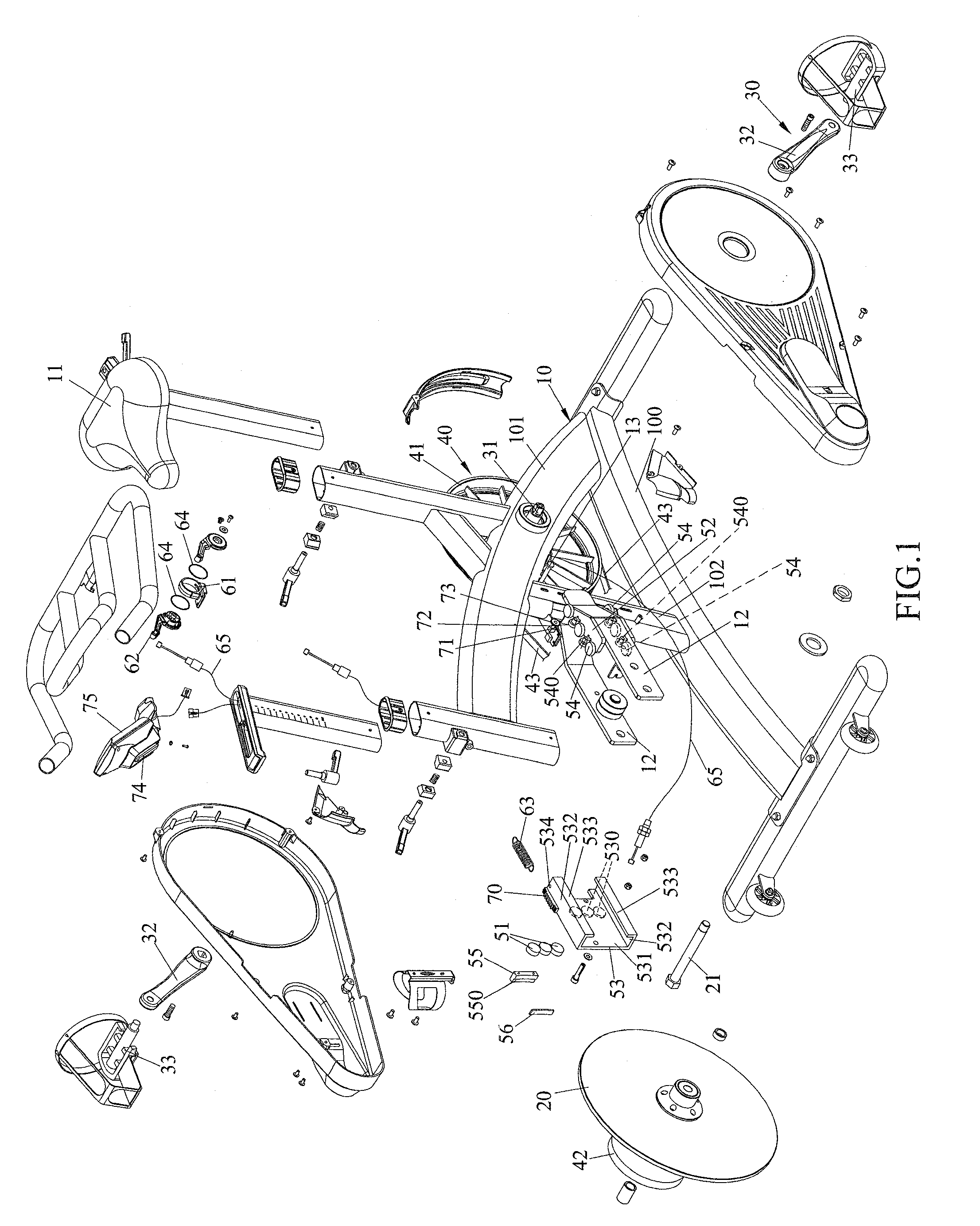
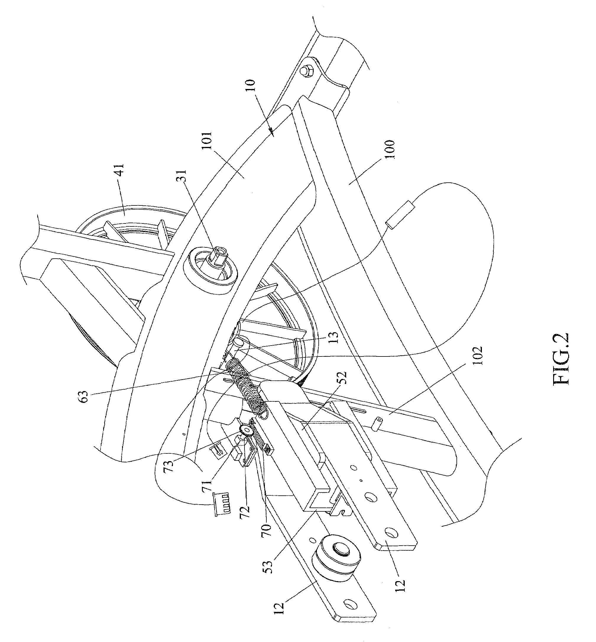
[0020]Referring to FIGS. 1 and 5-7, the present invention improves the magnets adjusting mechanism for an exerciser. The basic structure of a regular exerciser includes:

[0021]a frame assembly 10 allowing the exerciser to be firmly placed on a horizontal surface;

[0022]a flywheel 20 with a front shaft 21 to be rotatably mounted on the frame assembly 10;

[0023]a driving assembly 30 allowing reciprocal force to be applied by users;

[0024]a power transmission mechanism 40, with one power-input end linked with the driving assembly 30 and one power-output end linked with the flywheel 20, allowing the force applied by users to be transferred by the driving assembly 30, through the power transmission mechanism 40 to the flywheel 20, and the flywheel 20 to be rotated corresponding to the frame assembly 10; and

[0025]a magnets adjusting device 50 having at least a magnetic unit 51 near the flywheel 20 which will reciprocate with the magnetic unit 51 to generate magnetic damping while rotating aga...


PUM


Abstract

The present invention discloses an exerciser having magnets adjusting device, which comprises a frame assembly, a flywheel, a driving assembly, a power transmission mechanism and a magnets adjusting device. The magnets adjusting device includes a guiding rail, a sliding unit with magnetic units, and a control mechanism. The guiding rail is fixed on the frame assembly. The sliding unit is mounted on the guiding rail so that the sliding unit and the magnetic units can be linearly moved along the guiding rail. The control mechanism controls the reciprocated movement of the sliding unit and the magnetic units linearly close to or away from the axis of the flywheel. Whereby, to improve the stability of the adjusted variable damping and accurately calculate the corresponding resistance after the adjustment, and to enhance the durability of the machine can be achieved.

Description

FIELD OF THE INVENTION[0001]The present invention relates to an exerciser having magnets adjusting device, particularly to a magnets adjusting device with magnetic units of which can be linearly moved close to or away from the flywheel to adjust the magnetic resilience acted on the flywheel.BACKGROUND OF THE INVENTION[0002]According to the prior arts of exercisers, they basically comprise a frame assembly, a flywheel, a driving assembly and a power transmission mechanism. Reciprocation between the driving assembly and the flywheel is done through the power transmission mechanism. Inasmuch as the force applied by users is transmitted from the driving assembly, passed through the power transmission mechanism and then acted on the flywheel, the flywheel can be rotated correspondingly to the frame assembly. The prior arts of exercisers, used for increasing the workload of users to reach the goal of doing exercise, usually have a magnets adjusting device such as those disclosed in the U....

Claims


Application Information

Patent Timeline
IPC IPC(8): A63B22/06
CPCA63B21/0051A63B22/0605A63B2071/025A63B2225/68
Inventor LO, CHIU-HSIANG
Owner LO CHIU HSIANG
Why Eureka
Try Eureka