
Optical arrangement for the production of a light-sheet

a technology of optical arrangement and light sheet, which is applied in the field of optical arrangement for the production of light sheets, can solve the problems of inability to uniform illumination of inability to change the geometry of the light sheet, and inability to observe the specimen plane being examined. achieve the effect of greater efficiency

Inactive Publication Date: 2010-08-31
CARL ZEISS MICROSCOPY GMBH
View PDF9 Cites 54 Cited by
  • Summary
  • Abstract
  • Description
  • Claims
  • Application Information

AI Technical Summary

Benefits of technology

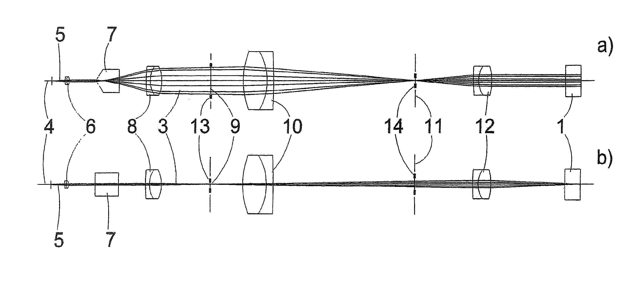
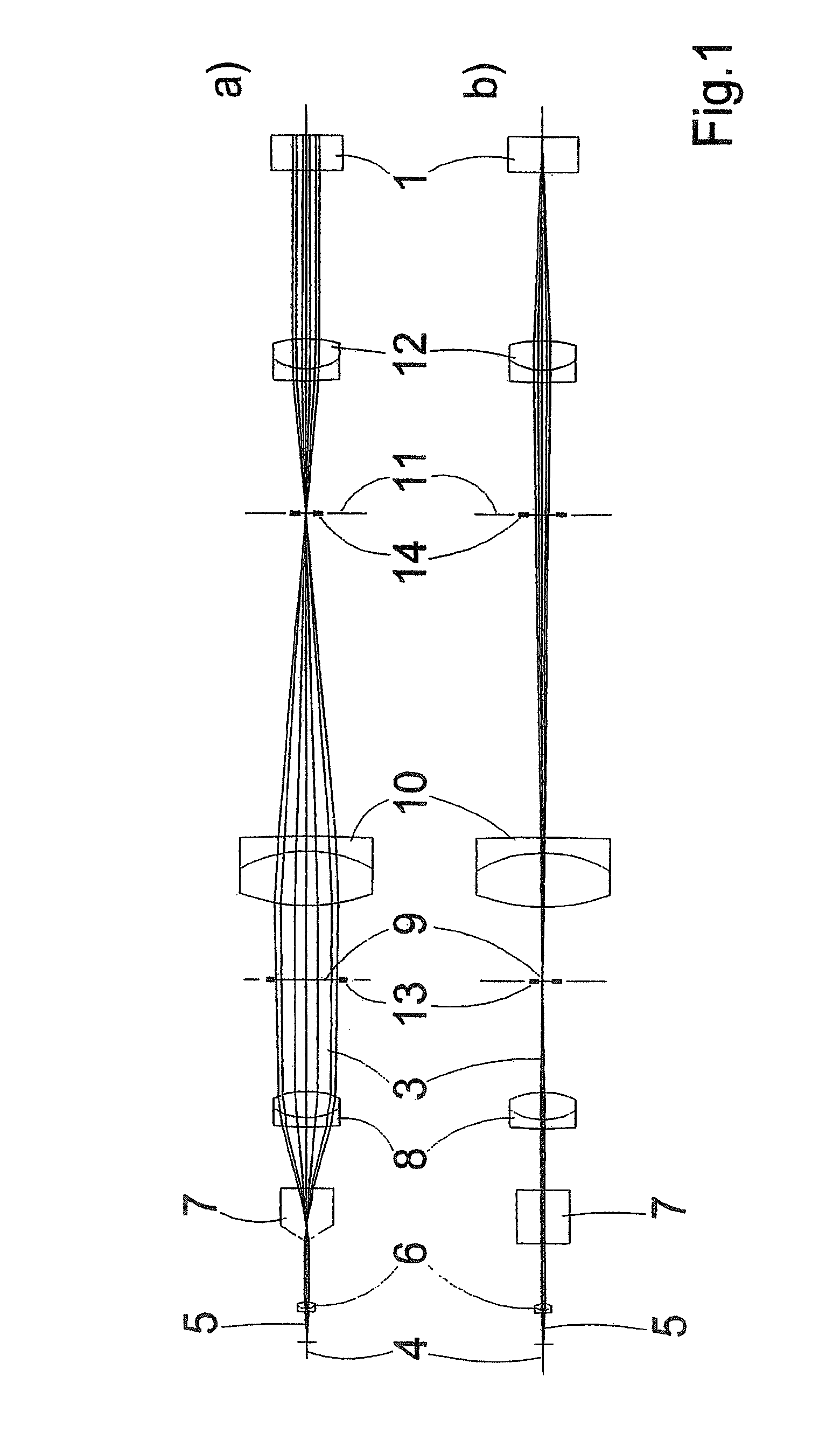
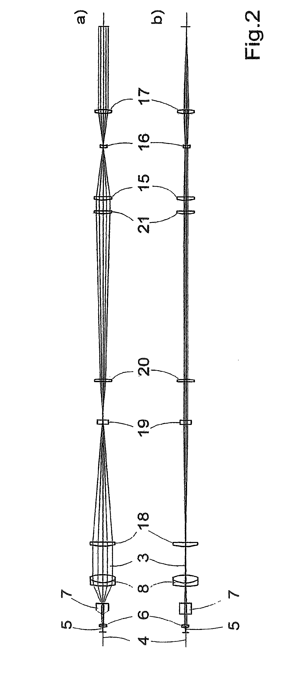
[0018]Proceeding from this prior art, it is the primary object of the invention to provide an optical arrangement for generating a light sheet which makes it possible to observe individual planes of a specimen with a greater efficiency than in previously known arrangements.
[0020]This makes it possible to adapt the geometry of the light sheet to the illumination requirements for observing one and the same specimen plane with a plurality of different objectives and, if required, to achieve a reduction in shadows occurring within the observed specimen plane as a result of the illumination.
[0034]Owing to the deflecting movement generated in this way, the direction of the beam components of the light sheet is influenced in such a way that these beam components strike the specimen substance successively in time in alternating directions so that shadows caused by opaque specimen substances within the illuminated specimen plane are prevented or at least substantially reduced.
[0038]In a third construction of the arrangement according to the invention, the light source comprises an array of individual laser light sources. Located downstream of these light sources are a cylindrical lens or GRIN lens extending over the entire array and collimating optics. Every laser light source completely illuminates the entire desired light sheet. The width of the light sheet in the Y-Z plane is determined by the emitted aperture of the laser light sources and the focal length of the collimating optics. The thickness of the light sheet in the X-Z plane is determined by the emitted aperture of the light sources and the focal lengths of the cylindrical optics and collimating optics. Because of the spatial arrangement of the laser light sources, every light source illuminates the specimen plane at a different angle so that shadows within the specimen plane are prevented or at least substantially reduced as was described above.

Problems solved by technology

This circumstance is particularly disadvantageous when one and the same plane of a specimen is to be imaged successively in time with different objectives whose optical imaging characteristics differ from one another.
Another disadvantage in the arrangements mentioned above is that the light sheet that is generated with them has a Gaussian intensity profile in cross section so that a uniform illumination of the specimen plane being examined is impossible.
This has the disadvantage that shadows result within the plane of the specimen being examined because of portions of the specimen substance which are not transparent for the illumination light and which lie in the illumination direction.
However, again, the geometry of the light sheet cannot be varied.
However, again the geometry of this light sheet can not be varied, specifically with respect to its thickness and length, so that an optimal illumination through the specimen plane to be examined is also impossible in this case when using different objectives whose optical characteristics differ from one another.
All of the arrangements mentioned above have the disadvantage of unwanted shadows within the plane of the specimen being examined which are caused by portions of the specimen substance in the illumination direction which are not transparent for the illumination light.

Method used


Image

  • Optical arrangement for the production of a light-sheet
  • Optical arrangement for the production of a light-sheet
  • Optical arrangement for the production of a light-sheet

Examples


Embodiment Construction

[0061]In FIG. 10, which will serve in the following for a brief explanation of the principle of selective plane illumination microscopy (SPIM) in the prior art, a specimen 1, for example, a biological substance, is surrounded by a transparent gel 2. This specimen 1 is a three-dimensional specimen 1 which extends in the drawing plane and perpendicular to the drawing plane. It will be assumed that the gel 2 is shaped to form a circular cylinder with an axis of rotation oriented perpendicular to the drawing plane.

[0062]As was already stated above, three-dimensional images of the specimen 1 are obtained on the basis of a plurality of optical sections through individual specimen planes by the SPIM technique. It will be assumed that the plane of the specimen 1 to be observed has the thickness d in the drawing plane.

[0063]In order to observe this plane, a light sheet 3 having a length 1 and a thickness d in the drawing plane which remains as uniform as possible along the entire length 1 an...


PUM


Abstract

The invention is directed to an optical arrangement with a light source for emitting a light bundle and with optical elements for transforming this light bundle into the shape of a light sheet, particularly suitable for illuminating individual planes of a three-dimensional specimen in selective plane illumination microscopy (SPIM). According to the invention, means are provided for varying the cross section of the light sheet, for varying the length of the light sheet and / or for influencing the direction in which individual beam components extending within the light sheet are directed to the specimen substance. This makes it possible to adapt the geometry of the light sheet to the illumination requirements for observing one and the same specimen plane with a plurality of different objectives and, if required, to reduce shadows occurring within the observed specimen plane as a result of the illumination.

Description

CROSS-REFERENCE TO RELATED APPLICATION[0001]This application claims priority of German Application No. 10 2007 015 063.8, filed Mar. 29, 2007, the complete disclosure of which is hereby incorporated by reference.BACKGROUND OF THE INVENTION[0002]a) Field of the Invention[0003]The invention is directed to an optical arrangement with a light source for emitting a light bundle and with optical elements for transforming this light bundle into the shape of a light sheet, particularly suitable for illuminating individual planes of a three-dimensional specimen in selective plane illumination microscopy (SPIM).[0004]b) Description of the Related Art[0005]In contrast to confocal laser scanning microscopy (LSM), in which a three-dimensional specimen is scanned point by point in individual planes of different depth and the image information thus acquired is then combined to form a three-dimensional image of the specimen, the SPIM technique relies on widefield microscopy and makes it possible to...

Claims


Application Information

Patent Timeline
IPC IPC(8): G02B21/06G02B9/08
CPCG02B21/0032G02B21/16G02B21/06G02B21/0076G02B26/08G02B27/0911
Inventor LIPPERT, HELMUTWALD, MATTHIASRADT, BENNO
Owner CARL ZEISS MICROSCOPY GMBH
Learn More