Apparatus for equalizing clipping noise signals of receiver systems and method thereof

a receiver system and clipping noise technology, applied in the field of methods and apparatus for correcting clipping distortion of receiver systems, can solve problems such as degrading a bit error rate (ber), distortion of transmission signals, etc., and achieve the effects of reducing system complexity, high reliability, and improving a ber of a system

Active Publication Date: 2010-08-31
SAMSUNG ELECTRONICS CO LTD +1
View PDF13 Cites 26 Cited by
  • Summary
  • Abstract
  • Description
  • Claims
  • Application Information

AI Technical Summary

Benefits of technology

[0007]Aspects of the present invention provide a method and apparatus for correcting clipping distortion of a receiver system, which can estimate an initial estimation value of a signal to have a comparatively high reliability, restore the signal, and improve a BER of a system by performing equalization using two equalization coefficients to acquire an estimation value of a clipped signal and an estimation value of a pre-clipped signal, and also can reduce system complexity by reducing a number of signal restorations.
[0008]Aspects of the present invention also provide a method and apparatus for correcting clipping distortion of a receiver system, which can reduce a decision error propagation that may occur when restoring a clipped signal.
[0009]Aspects of the present invention also provide a method and apparatus for correcting clipping distortion of a receiver system, which can utilize an optimal equalizer for each of a clipped signal and a non-clipped signal of a transmission signal, which is required during a decision-aided reconstruction (DAR) and an iterative amplitude restructure (IAR) signal restoration process, and thereby can restore a signal by considering both an additive white Gaussian noise (AWGN) and clipping noise.

Problems solved by technology

However, the clipping method may cause a distortion of a transmission signal and thereby degrade a Bit Error Rate (BER).

Method used


Image

  • Apparatus for equalizing clipping noise signals of receiver systems and method thereof
  • Apparatus for equalizing clipping noise signals of receiver systems and method thereof
  • Apparatus for equalizing clipping noise signals of receiver systems and method thereof

Examples


Embodiment Construction

[0020]Reference will now be made in detail to exemplary embodiments of the present invention, examples of which are illustrated in the accompanying drawings, wherein like reference numerals refer to the like elements throughout. The exemplary embodiments are described below in order to explain the present invention by referring to the figures.

[0021]When detailed descriptions related to a well-known related function or configuration are determined to make the spirits of the present invention ambiguous, the detailed descriptions will be omitted herein. Also, terms used throughout the present specification are used to appropriately describe exemplary embodiments of the present invention, and thus may be different depending upon a user and an operator's intention, or practices of application fields of the present invention. Therefore, the terms must be defined based on descriptions made through the present invention.

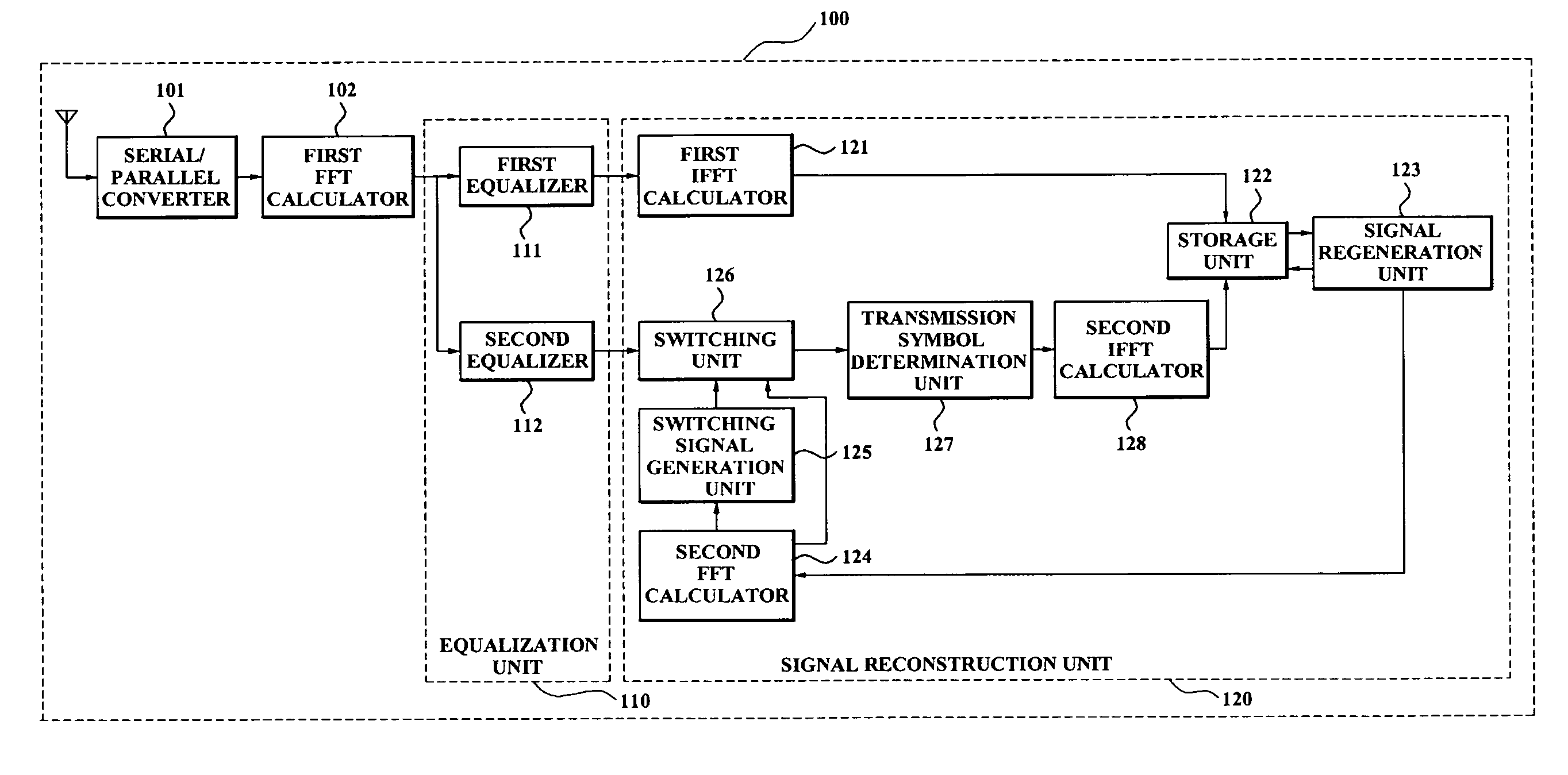
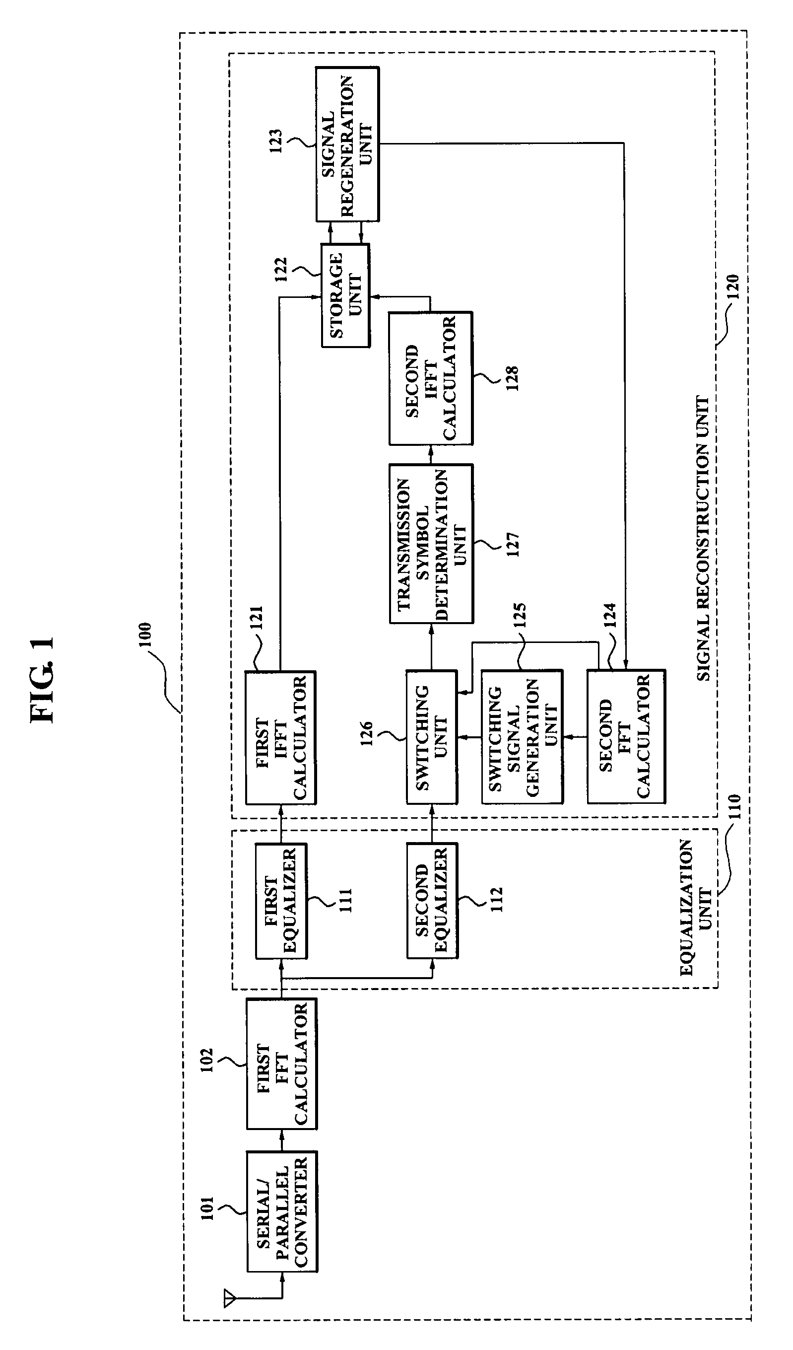
[0022]FIG. 1 is a block diagram illustrating an apparatus for correctin...


PUM


Abstract

An apparatus for correcting clipping distortion of a receiver system includes: an equalizer which generates a first equalization signal by equalizing a frequency domain clipping signal via a first equalization coefficient correcting a channel distortion, and generates a second equalization signal by equalizing the frequency domain clipping signal via a second equalization coefficient correcting the clipping distortion and the channel distortion; and a signal reconstruction unit which receives the first equalization signal and the second equalization signal from the equalizer, determines a transmission symbol by performing a hard decision with respect to the second equalization, and reconstructs a signal by using an amplitude of the transmission symbol and a phase of the first equalization signal when a level of the amplitude of the transmission symbol is greater than or equal to a reference value.

Description

CROSS-REFERENCE TO RELATED APPLICATION[0001]This application claims priority from Korean Patent Application No. 10-2006-0100263, filed on Oct. 16, 2006, in the Korean Intellectual Property Office, the entire disclosure of which is incorporated herein by reference.BACKGROUND OF THE INVENTION[0002]1. Field of the Invention[0003]Methods and apparatuses consistent with the present invention relate to a method and apparatus for correcting clipping distortion of a receiver system, and more particularly, to a method and apparatus for correcting a signal distortion caused by clipping, which occurs when clipping is performed to reduce a peak-to-average ratio (PAPR) in a wideband wireless communication system including an Orthogonal Frequency Division Multiplexing (OFDM) scheme.[0004]2. Description of Related Art[0005]Multi-carrier transmission schemes, such as an Orthogonal Frequency Division Multiplexing (OFDM) scheme, a Filtered Multitone (FMT) scheme, and the like, are robust against adve...

Claims


Application Information

Patent Timeline
Patent Type & Authority Patents(United States)
IPC IPC(8): H04B15/00
CPCH04L25/03006H04L27/2623H04L2025/03414H04B1/10H04B1/18H04L27/26
Inventor KIM, YOUNG-DOOKIM, EUNG SUNLIM, GI HONGKWON, UI KUN
Owner SAMSUNG ELECTRONICS CO LTD
Why Eureka
Try Eureka