Double phase encoding quantum key distribution

a quantum key and double phase technology, applied in the field of network communication, can solve the problems of reducing the security level of public key encryption, difficult to reverse calculate, and difficult to calculate for the computer, and achieve the effect of enhancing the bit ra

Inactive Publication Date: 2010-08-31
RPX CLEARINGHOUSE
View PDF23 Cites 26 Cited by
  • Summary
  • Abstract
  • Description
  • Claims
  • Application Information

AI Technical Summary

Benefits of technology

[0011]It will thus be appreciated by persons skilled in the art that quantum key distribution in accordance with certain embodiments of the invention enables use of multi-photon pulses without unacceptable loss of security, thereby enhancing the bit rate with which a quantum key can be distributed securely.

Problems solved by technology

Public key encryption utilizes “one-way functions” that are relatively simple for computers to calculate, but difficult to reverse calculate.
In particular, a one way function ƒ(x) is relatively easy for a computer to calculate given the variable x, but calculating x given ƒ(x) is difficult for the computer, although not necessarily impossible.
However, advances in the capabilities of computers tend to erode the level of security provided by public key encryption because the difficulty of reverse calculating the one-way function decreases as computing capabilities increase.
However, in modern communication networks the distribution of Vernam cipher keys is often impractical, e.g., because the keys can be quite long and key distribution itself is subject to eavesdropping.
In particular, it is not possible to measure an unknown quantum state of a photon without modifying it.
Hence, an eavesdropper attempting to intercept the key would introduce detectable errors into the key.
Unfortunately, photon-per-bit key distribution is so inefficient with current technology as to be impractical.

Method used


Image

  • Double phase encoding quantum key distribution
  • Double phase encoding quantum key distribution
  • Double phase encoding quantum key distribution

Examples


Embodiment Construction

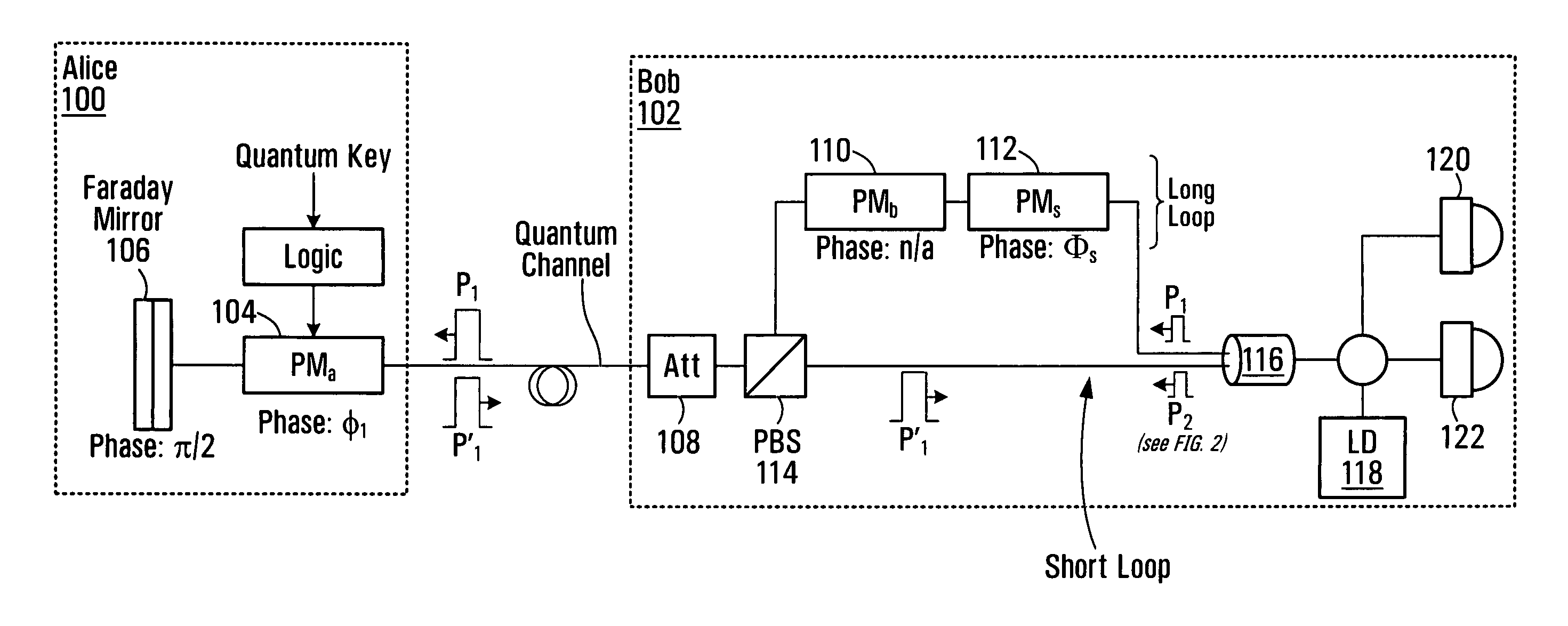
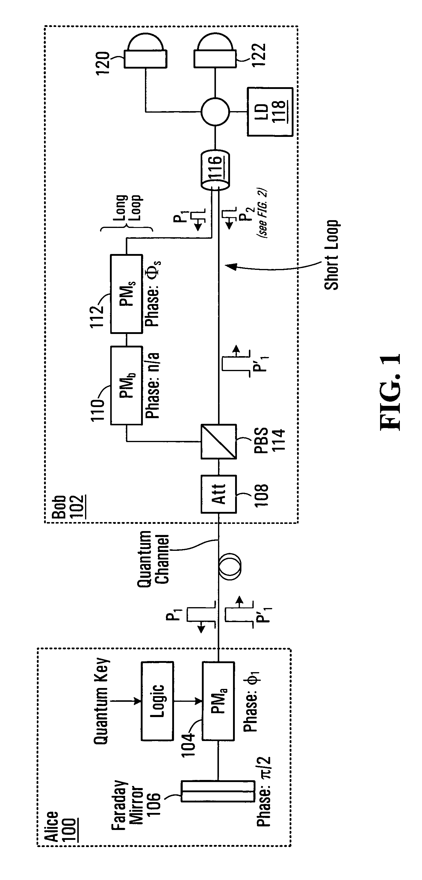
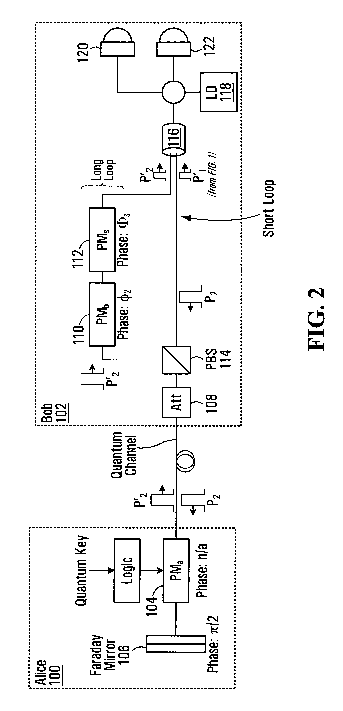
[0017]FIGS. 1 and 2 illustrate a first node 100 (also referred to as “Alice”) and a second node 102 (also referred to as “Bob”) of a communications network. Alice 100 and Bob 102 employ double phase encoding quantum key distribution (“QKD”). Alice 100, the sender of a quantum key having a plurality of quantum key bits, includes a phase modulator PMa 104 and a Faraday Mirror 106. Bob 102, the recipient of the quantum key, includes an attenuator 108, phase modulator PMb 110, phase modulator PMs 112, Polarization Beam Splitter (PBS) 114, a coupler (and / or beamsplitter) 116, a photon source 118 (e.g., a laser diode), and a detection unit (including a detector 120 triggered by a pulse affected with constructive interference and a detector 122 triggered by a pulse affected with destructive interference).

[0018]A series of short laser pulses is employed for quantum key distribution between Alice 100 and Bob 102. The short laser pulses are generated by the laser diode 118 at Bob 102. Conside...


PUM


Abstract

A method of distributing a quantum key from a sender to a recipient. The recipient generates a pulse having multiple photons; splits the pulse into first and second sub-pulses; phase modulates the first sub-pulse with a secret key; and transmits both the phase-modulated first sub-pulse and the second sub-pulse to the sender. The sender receives the phase-modulated first sub-pulse and the second sub-pulse from the recipient; encodes a quantum key bit into one of the sub-pulses received from the recipient; and transmits both the phase-modulated first sub-pulse and the second sub-pulse back to the recipient. Then, the recipient receives the phase-modulated first sub-pulse and the second sub-pulse from the sender; phase modulates the second sub-pulse with the secret key; combines the phase-modulated first sub-pulse and the phase-modulated second sub-pulse to produce a composite pulse; and processes the composite pulse in an attempt to detect the quantum key bit.

Description

CROSS-REFERENCE TO RELATED APPLICATIONS[0001]The present application is a CONTINUATION under 35 USC §120 of PCT International Patent Application bearing Serial No. PCT / CA2006 / 000644, filed on Apr. 24, 2006, and is hereby incorporated by reference; the present application also claims the benefit of priority under 35 USC §119(e) of U.S. Provisional Patent Application Ser. No. 60 / 872,425, filed on Sep. 30, 2005, and is incorporated herein by reference.[0002]The present application claims the benefit under 35 USC §120, and is a CONTINUATION-IN-PART, of U.S. patent application Ser. No. 11 / 241,164 to Kuang et al., filed on Sep. 30, 2005, hereby incorporated by reference herein.FIELD OF THE INVENTION[0003]This invention relates generally to the field of network communications, and more particularly to communications over a quantum channel.BACKGROUND[0004]Public key encryption is currently a popular technique for secure network communications. Public key encryption utilizes “one-way functio...

Claims


Application Information

Patent Timeline
Patent Type & Authority Patents(United States)
IPC IPC(8): H04L9/00
CPCH04L9/0858
Inventor KUANG, RANDYWANG, GUO QIANGSTANKUS, JOHN
Owner RPX CLEARINGHOUSE
Why Eureka
Try Eureka